
Microgrid operation method and system containing electric automobile power conversion station under demand side response

A demand-side response and electric vehicle technology, applied in photovoltaic power generation, circuit devices, AC network circuits, etc.

Inactive Publication Date: 2019-04-26
HUAZHONG UNIV OF SCI & TECH
View PDF4 Cites 0 Cited by
  • Summary
  • Abstract
  • Description
  • Claims
  • Application Information

AI Technical Summary

Problems solved by technology

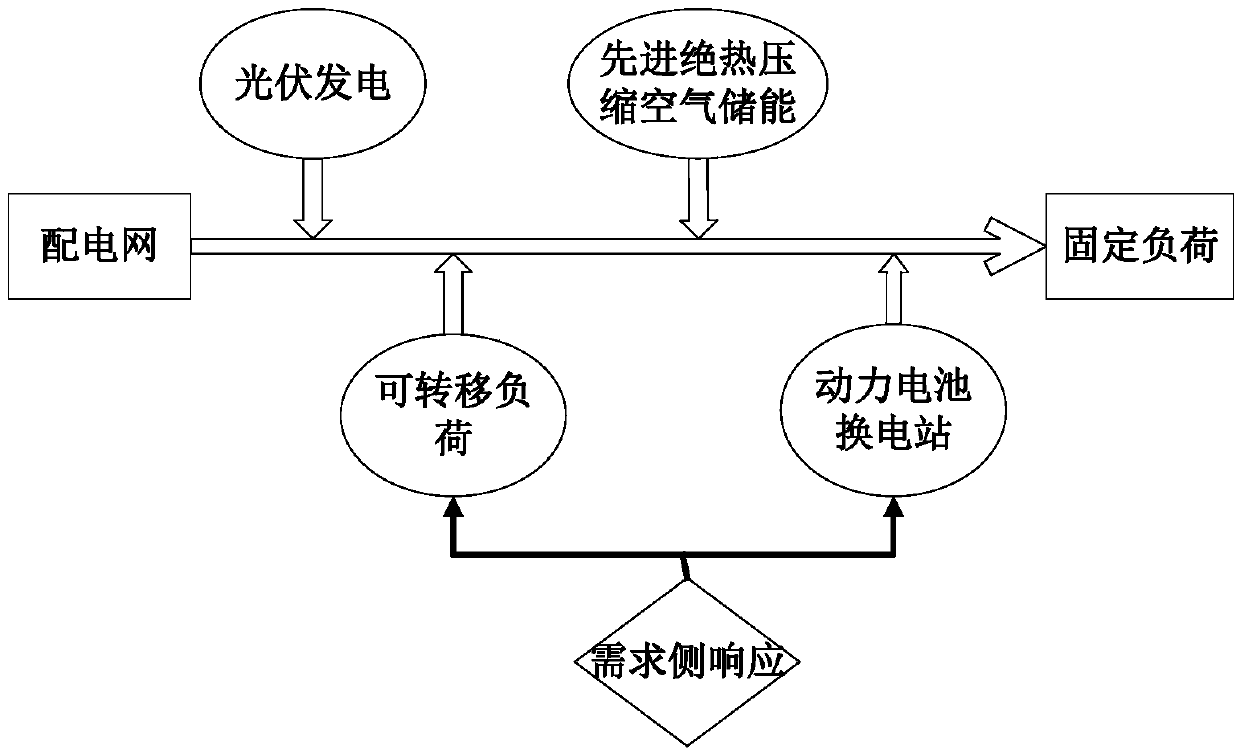
[0004] In view of the above defects or improvement needs of the prior art, the present invention provides a microgrid operation method and system including electric vehicle substations under the consideration of demand side response, thus solving the problem of photovoltaic storage grid-connected microgrid including electric vehicles , using advanced adiabatic compressed air energy storage as an energy storage method, and comprehensively considering the technical issues of microgrid demand-side response research

Method used


Image

  • Microgrid operation method and system containing electric automobile power conversion station under demand side response
  • Microgrid operation method and system containing electric automobile power conversion station under demand side response
  • Microgrid operation method and system containing electric automobile power conversion station under demand side response

Examples


Embodiment Construction

[0026] In order to make the object, technical solution and advantages of the present invention clearer, the present invention will be further described in detail below in conjunction with the accompanying drawings and embodiments. It should be understood that the specific embodiments described here are only used to explain the present invention, not to limit the present invention. In addition, the technical features involved in the various embodiments of the present invention described below can be combined with each other as long as they do not constitute a conflict with each other.

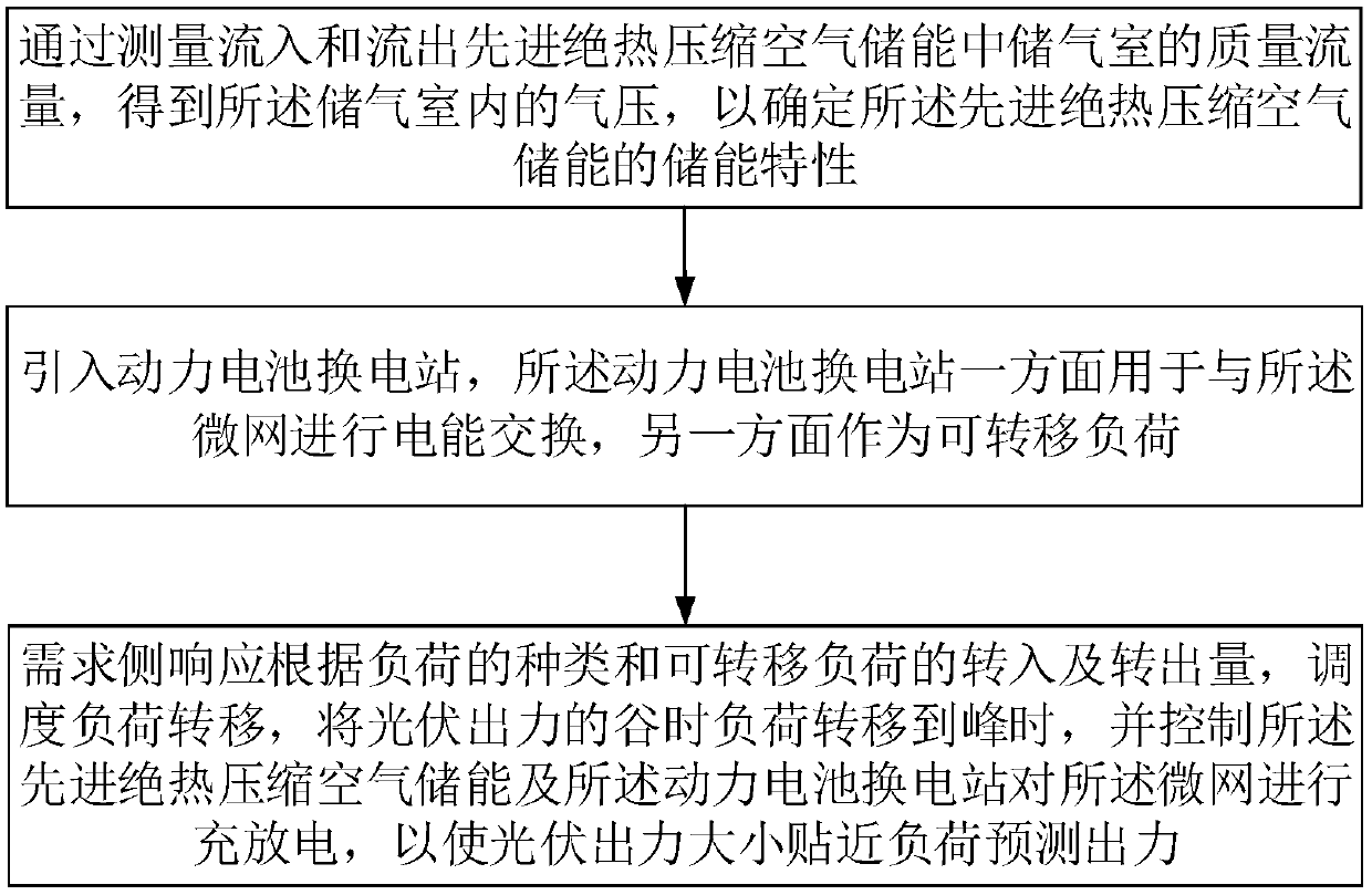
[0027] Such as figure 1 Shown is a schematic flowchart of a micro-grid operation optimization method including electric vehicle substations under the consideration of demand side response provided by the embodiment of the present invention, which specifically includes the following steps:

[0028] (1) Determine the input, output and model parameters of the microgrid optimization simulation mode...


PUM


Abstract

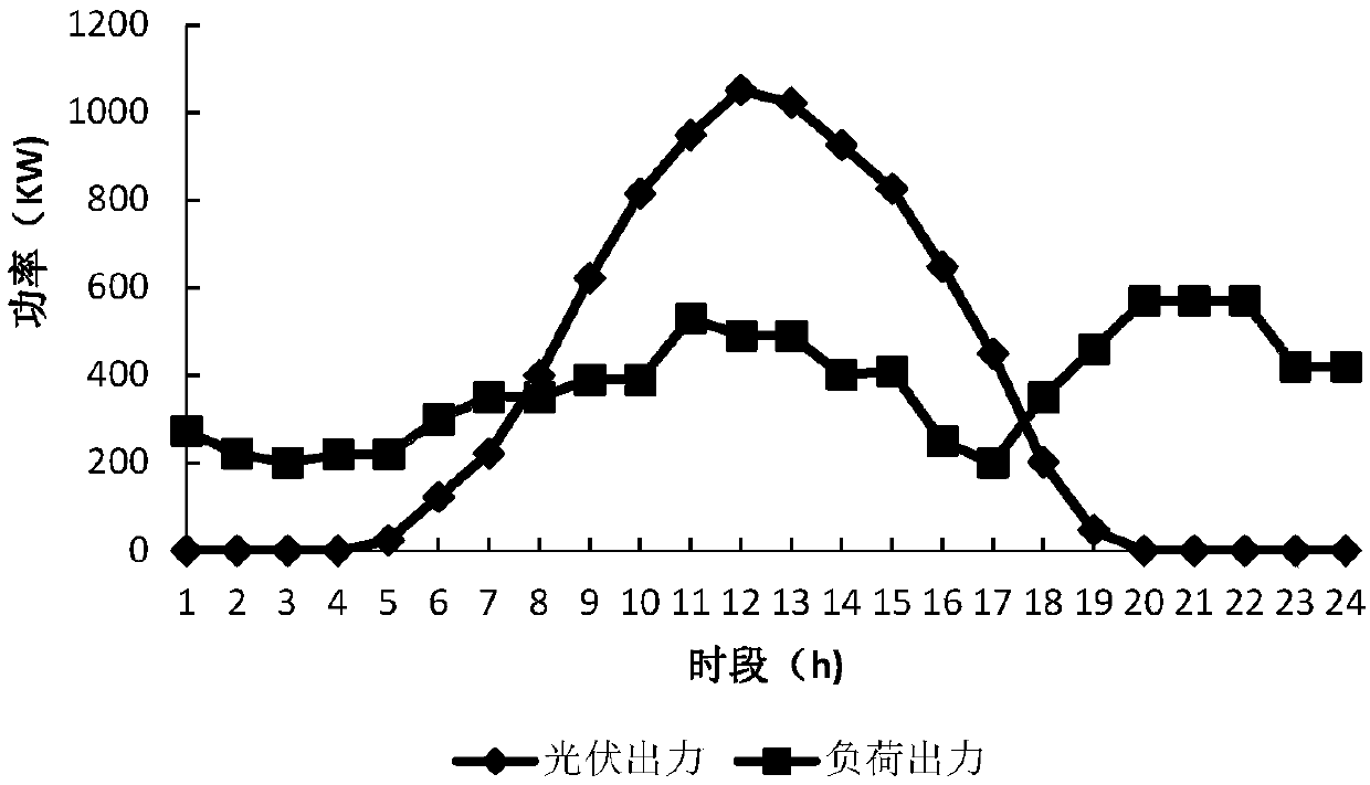
The invention discloses a microgrid operation optimization method and system containing an electric automobile power conversion station under consideration of demand side response. Firstly, the air pressure in an air storage chamber is obtained by measuring the mass flow flowing into and out of an advanced adiabatic compressed air energy storage air storage chamber so as to determine the energy storage characteristic of the advanced adiabatic compressed air energy storage; a power battery power conversion station is introduced, wherein the power battery power conversion station is used for carrying out electric energy conversion with a microgrid on one hand and is also used as a transferable load on the other hand; and under the demand side respond, load transfer is dispatched according tothe type of the load and the transfer-in and transfer-out amount of the transferable load, the valley-time load of photovoltaic output power is transferred to the peak time, the advanced adiabatic compressed air energy storage is controlled, and the power battery power conversion station is controlled to charge and discharge the microgrid, so that the photovoltaic output power is close to predicted output power of the load. According to the method and the system, the system gain can be maximized, the photovoltaic power generation utilization rate can be increased, the energy storage capacityconfiguration can be optimized, and the renewable energy utilization rate can be improved.

Description

technical field [0001] The invention belongs to the field of system simulation modeling, and more specifically relates to a microgrid operation method and system including electric vehicle swapping stations under demand-side response. Background technique [0002] The energy crisis and environmental pollution are becoming more and more serious. Renewable energy distributed power supply and electric vehicles are getting more and more attention in the development of future energy structure. It has become a research focus and development trend of the current electric power industry. At present, the most widely used energy storage method in the microgrid is the hybrid energy storage of batteries and supercapacitors. However, the cost of the battery is high, the life is short, and the discarded battery will cause secondary pollution to the environment. The advanced adiabatic compressed air energy storage (AA-CAES) system has attracted the attention of the international communit...

Claims


Application Information

Patent Timeline
IPC IPC(8): H02J3/28
CPCH02J3/28H02J2203/20Y02E10/56Y02E70/30
Inventor 刘君瑶苗世洪李姚旺
Owner HUAZHONG UNIV OF SCI & TECH
Learn More