
Infrared generator

An infrared generator, infrared radiation technology, applied in the direction of ohmic resistance electrodes, heating elements, heating element materials, etc., can solve the problems of low safety, unconcentrated energy, reduced radiation power energy density, etc., to improve the aggregation effect, The effect of reducing the overall power and reducing the overall size

Pending Publication Date: 2019-04-26
江苏华旦科技有限公司
View PDF8 Cites 0 Cited by
  • Summary
  • Abstract
  • Description
  • Claims
  • Application Information

AI Technical Summary

Problems solved by technology

[0004] However, this way to obtain infrared rays, due to the low efficiency of the infrared radiation characteristics of the heating material, the efficiency of the infrared source made in this way is relatively low; and usually the temperature of the heating element is high, easy to catch fire or cause burns, and the safety is not high. ; and it is often accompanied by relatively strong visible light radiation, which is undesirable in some applications
[0005] In order to take care of safety, such products often need to reduce the temperature of the heating element to a relatively low level. In this way, the power and power density of the infrared rays radiated by the infrared radiation source will often be greatly reduced, making the application effect great. discount
[0006] In addition, moreover, the current usual thermal infrared radiation source, when thermally radiating infrared rays, usually radiates 360 degrees in all directions of the radiation source at the same time, and for plate-shaped ones, it will radiate infrared rays to the six sides of the plate at the same time. Radiation energy has no directionality, so that the energy in a certain direction is not concentrated and dispersed, and the energy density of radiation power will be greatly reduced.

Method used


Image

  • Infrared generator
  • Infrared generator
  • Infrared generator

Examples


Embodiment

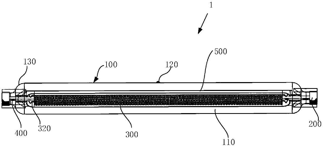
[0055] figure 1 It is the structural representation of the infrared generator involved in the embodiment;

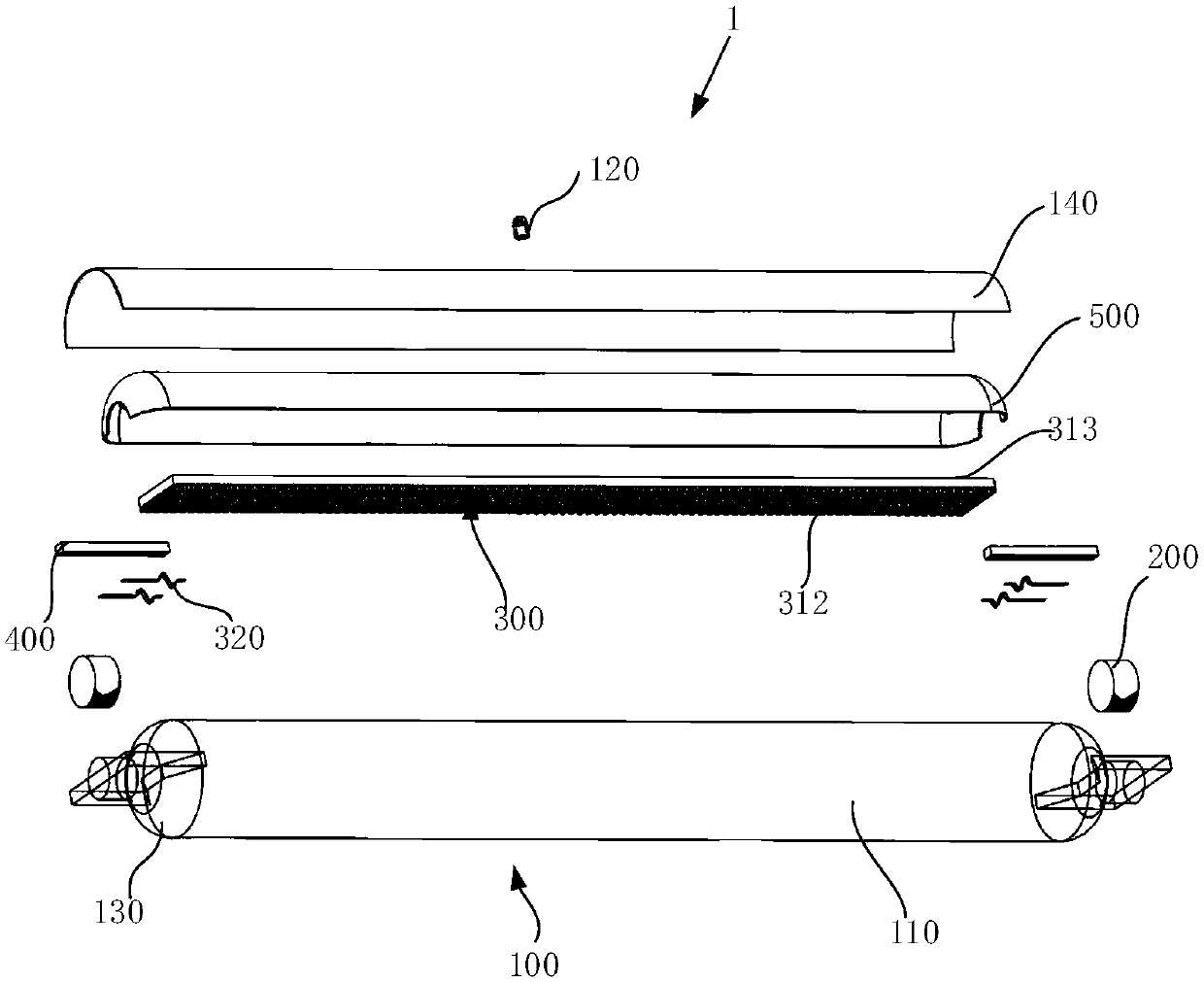
[0056] figure 2 It is an exploded exploded view of the infrared generator involved in the embodiment.

[0057] The infrared generator 1 provided in this embodiment includes: a quartz container 100 , two external electrodes 200 , an infrared radiation element 300 , two internal electrodes 400 and an infrared reflection element 500 .

[0058] The quartz container 100 has an internal cavity 110, and the internal cavity 110 is a vacuum. In this embodiment, the range of the vacuum degree of the internal cavity 110 is less than or equal to 1 Torr (torr). At this time, it can be considered that the heat of the internal cavity 110 Convection is eliminated, thereby reducing heat loss to produce mainly the required infrared radiation. The appearance of the quartz container 100 can be in various shapes, as long as the wall is sealed so that the inner cavity 110 forms a vacuum s...


PUM


Abstract

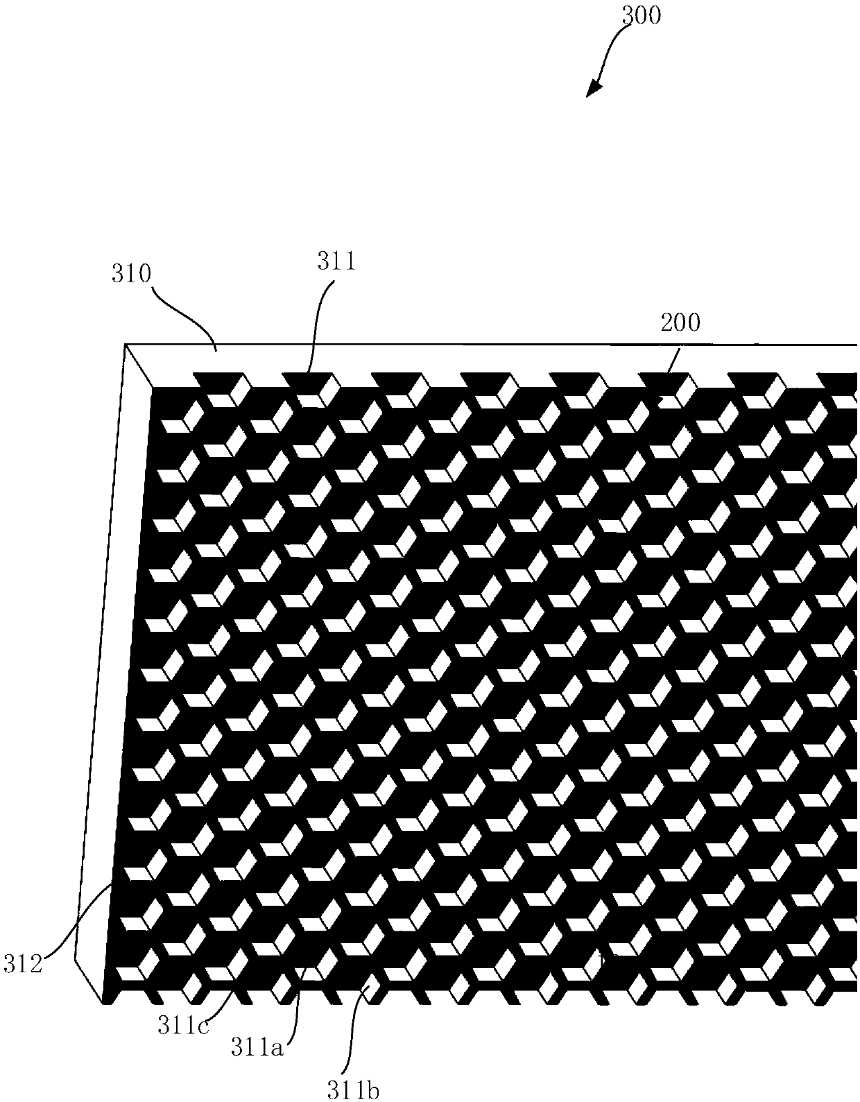
The invention provides an infrared generator. The infrared generator is capable of greatly improving the radiation coefficient of a middle infrared ray and improving the directionality of the radiation. The infrared generator is characterized by comprising a quartz container provide with an internal cavity, two external electrodes correspondingly and separately disposed on the two end faces of thewalls of the quartz container, an infrared radiation member and two internal electrodes separately corresponding to the two external electrodes, wherein the infrared radiation member comprises a radiation body, and at least one surface of the radiation body is provided with a plurality of radiating surfaces of pits formed by the surface depression and uniformly distributed; and the pits are provided with pit bottoms disposed at the bottom ends, pit walls surrounding the pit bottoms and formed by extending outwardly along the pit bottoms and pit openings arranged at the top ends of the pit walls, each pit meets: D / R1 is greater than or equal to 1, wherein D is the depth of the pits, R1 is the radius of the pit openings of the pits, and the radius of the pit openings is the radius of circles which can just cover the pit openings.

Description

technical field [0001] The invention relates to an infrared generator, in particular to an infrared generator which can greatly improve the radiation coefficient of mid-infrared rays and improve the directivity of radiation. Background technique [0002] The generation of mid-to-far infrared rays is a rather troublesome thing. Usually, the method of heating the object and making the object generate thermal radiation is used to obtain the mid-long wave infrared ray. [0003] The commonly used method is to use electricity to pass through a section of heating wire, molybdenum wire or tungsten wire to make the heating wire, molybdenum wire or tungsten wire generate heat, and the temperature rises to 2000°C-2700°C, which directly causes the heating wire or tungsten wire to generate thermal radiation, thereby emits infrared rays. [0004] However, this way to obtain infrared rays, due to the low efficiency of the infrared radiation characteristics of the heating material, the eff...

Claims


Application Information

Patent Timeline
Patent Type & Authority Applications(China)
IPC IPC(8): H05B3/44H05B3/02H05B3/03H05B3/08H05B3/12
CPCH05B3/02H05B3/03H05B3/08H05B3/12H05B3/44
Inventor 盛书华
Owner 江苏华旦科技有限公司
Learn More