Disc hydraulic anti-lock brake and brake system

An anti-lock and brake technology, applied in the direction of brakes, brake types, brake transmission devices, etc., can solve the problems of large occupied space, difficult implementation, poor heat dissipation effect, etc., and achieve easy implementation and anti-lock braking. Effect

Active Publication Date: 2019-04-26
QINGDAO XUZHOU CONSTR MASCH SALE & SERVICE CO LTD
View PDF9 Cites 0 Cited by
  • Summary
  • Abstract
  • Description
  • Claims
  • Application Information

AI Technical Summary

Problems solved by technology

[0003] At present, the existing vehicles on the market have drum brakes and disc brakes, and most of the disc brakes are used on small cars. Most of the commercial vehicles still have drum brakes and most of them are air-controlled. Low-speed vehicles use hydraulic control and oil-air hybrid braking. Although they can all achieve braking to slow down and stop the vehicle, they have the disadvantages of taking up a lot of space, difficult to arrange, poor braking performance, worse heat dissipation, and braking. The system has many shortcomings such as complex structure, poor effect, high cost, and inconvenient operation.
[0004] The existing ABS (Ant-ilock Brake System, anti-lock braking system) on the market can also reduce or optimize the impact of braking inertia on motor vehicle braking, but the existing ABS is due to its complex structure and safety factor Low and high cost, so the existing ABS cannot be widely promoted
[0005] The inventor applied on August 19, 2014, the application number is 2014104098460, and the invention name is the Chinese invention patent of hydraulic anti-lock brake wheel cylinder and axle brake system. Although the above problems have been solved, the processing is difficult and the realization difficulty

Method used


Image

  • Disc hydraulic anti-lock brake and brake system
  • Disc hydraulic anti-lock brake and brake system
  • Disc hydraulic anti-lock brake and brake system

Examples


Embodiment approach 1

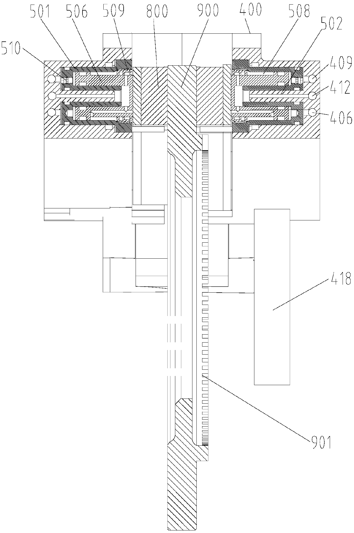
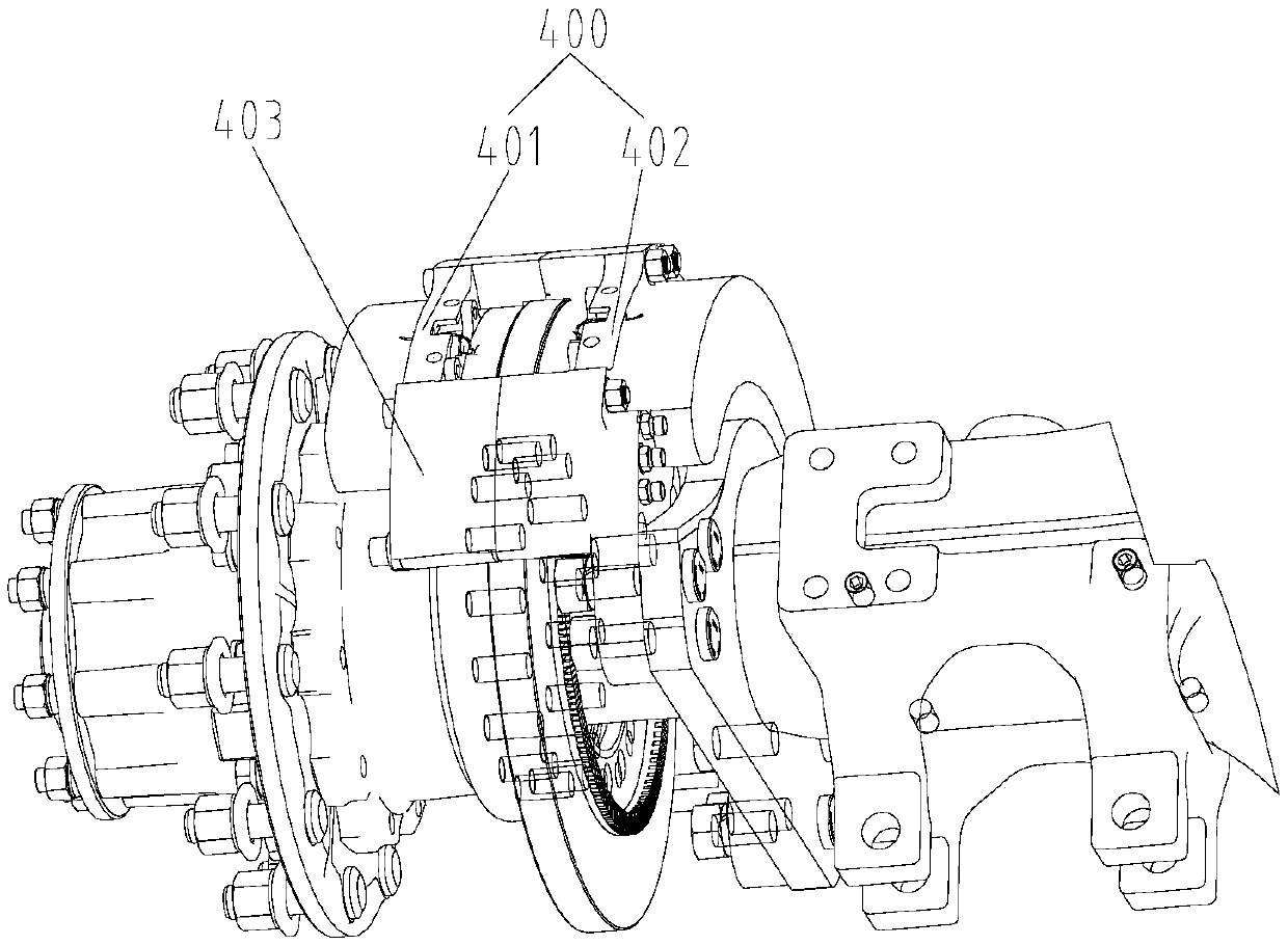
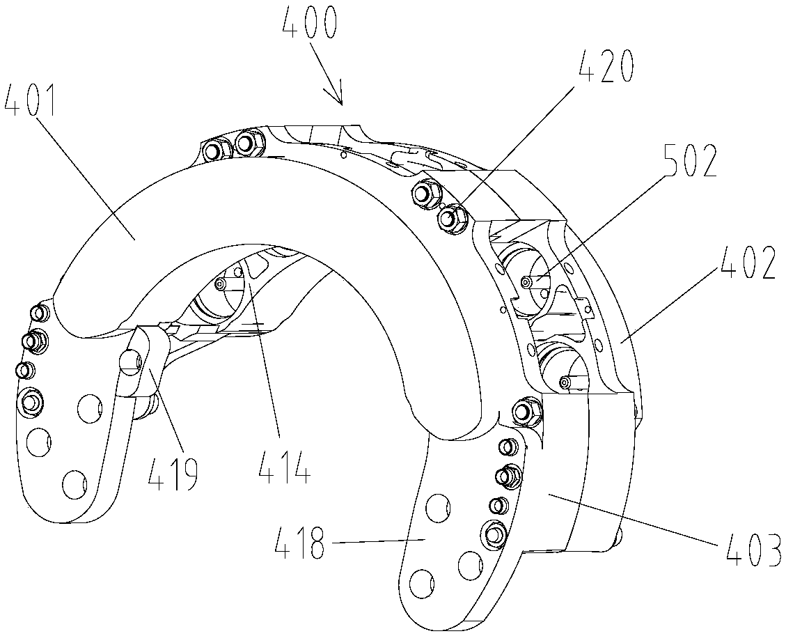
[0062] Such as Figure 1 to Figure 9 , Figure 13 to Figure 21 As shown, the present invention provides a disc hydraulic anti-lock brake, which includes a bracket 400, a first piston 501, a second piston 506, an elastic body 505, a brake pad 800, a brake disc 900, a release brake system and an anti-lock brake. dead brake system. Wherein, the first piston 501 is accommodated in the first cavity 415 of the bracket 400, and the first piston 501 can move axially in the first cavity 415, and the second piston 506 is accommodated in the second cavity 504 of the first piston 501, And the second piston 506 can move axially in the second cavity 504, and the end cap 509 covers the opening of the second cavity 504 and is fixedly connected with the second cavity 504 to limit the first piston 501 and the second piston 506. The limit motion stroke, the elastic body 505 is arranged between the second piston 506 and the bottom of the second cavity 504 to apply pressure to the first piston 5...

Embodiment approach 2

[0077] Such as Figure 10 to Figure 12 As shown, the present invention also provides a disc type hydraulic anti-lock brake, which differs from Embodiment 1 in that the first cavity 416 provided on the bracket 400 is used to accommodate the first piston 601 , and the second hole 416 provided on the bracket 400 The cavity 417 is used to accommodate the second piston 701 , the first cavity 416 and the second cavity 417 are arranged alternately, and according to these structural changes, the structures of the first piston 601 and the second piston 701 are adaptively changed.

[0078]Specifically, the disc hydraulic anti-lock brake includes: a bracket 400, which is provided with a first cavity 416, a second cavity 417, a core pipe 704, a channel, and brake pads arranged at the openings of the first cavity 416 and the second cavity 417. Seat and the mounting part for installing the bracket to the axle, the channel includes a first channel 406, a second channel 412 and a third channe...

Embodiment approach 3

[0082] Such as figure 1 , figure 2 with Figure 21 As shown, the present invention also provides a disc hydraulic anti-lock braking system, which is applied to the braking of motor vehicles, of course, it is not limited to automobiles, and it can also be applied to non-automotive braking, such as high-speed rail A braking system, the disc hydraulic anti-lock braking system includes a liquid container 103, a liquid pump, a liquid charging valve, an accumulator, a service brake valve, a parking brake valve, an axle 102, and a first pipeline 201 , the second pipeline 202, the third pipeline 203 and the disc hydraulic anti-lock brake; the disc hydraulic anti-lock brake is the disc hydraulic anti-lock brake described in Embodiment 1, its structure and working principle are the same and will not be repeated here;

[0083] When the liquid pump is working, the liquid in the liquid container 103 enters the accumulator under the action of the liquid pump and the filling valve and is...


PUM


Abstract

A disc hydraulic anti-lock brake and a brake system are provided. The disc hydraulic anti-lock brake includes a support (400) provided with a first opening (415), a core tube (502), a first passage (406), a second passage (412), a third passage (409) and a braking sheet base; a first piston (501) disposed in the first opening (415), with a first cavity being communicated with the first passage (406) and a service brake valve, and the first piston (501) being provided with a second opening (504); a second piston (506) disposed in the second opening (504), with a second cavity (508) being communicated with the core tube (502), the second passage (412) and a parking brake valve; an elastic member (505) disposed between the second piston (506) and the bottom of the second opening (504); a braking terminating system provided with a pump (315) and an unloading valve (322); a braking disc (900) provided with a counting gear ring and a mounting portion; and an anti-lock system provided with acounting sensor, a motor (309), and a liquid drainage valve (310). A liquid inlet of the liquid drainage valve (310) is communicated with the first cavity through the third passage (409). According tothe brake, the support (400) is provided with the first opening (416) and the second opening (417), and the first piston (601) and the second piston (701) are disposed in the first opening (416) andthe second opening (417) respectively. The brake system can achieve service braking, parking braking and anti-lock braking, and is easy to achieve.

Description

technical field [0001] The invention relates to the field of braking, in particular to a disc hydraulic anti-lock brake and a braking system used for equipment including rotational motion of wheels and the like. Background technique [0002] With the increasing number of various vehicles, machinery and other equipment, people have higher and higher requirements for safe and energy-saving use of vehicles, machinery and other equipment, and the quality of braking performance is an important factor for the safe operation of vehicles and machinery. in accordance with. Especially in the case of fast vehicle speed and heavy weight, braking inertia has more and more influence on safe driving. How to reduce and optimize the impact of braking inertia on equipment braking including vehicles and machinery (such as hoisting) , is a problem that all people in the industry need to work tirelessly to solve. [0003] At present, the existing vehicles on the market have drum brakes and dis...

Claims


Application Information

Patent Timeline
IPC IPC(8): F16D55/228F16D65/16B60T13/74F16D121/04
CPCF16D55/228F16D65/16B60T13/745F16D2121/04F16D2125/06F16D65/183F16D2121/06F16D2121/14B60T13/22F16D2055/002B60T8/329
Inventor 吴茂庭
Owner QINGDAO XUZHOU CONSTR MASCH SALE & SERVICE CO LTD
Why Eureka
Try Eureka