Shower gel pouring system

A filling system and shower gel technology, applied in packaging, bottle filling, liquid bottling, etc., can solve the problems of high operator requirements, inability to meet production needs, low work efficiency, etc., reducing labor intensity, filling and filling. High efficiency and the effect of improving work efficiency

Active Publication Date: 2019-04-30
广州汇芬生物科技有限公司
View PDF9 Cites 14 Cited by
  • Summary
  • Abstract
  • Description
  • Claims
  • Application Information

AI Technical Summary

Problems solved by technology

In the actual production process, the filling of liquids is generally carried out manually, and the requirements for operators are relatively high. Especially when quantitative filling is required, the error of manual filling is large, and the work efficiency is low. Meet production needs

Method used


Image

  • Shower gel pouring system
  • Shower gel pouring system
  • Shower gel pouring system

Examples


specific Embodiment approach 1

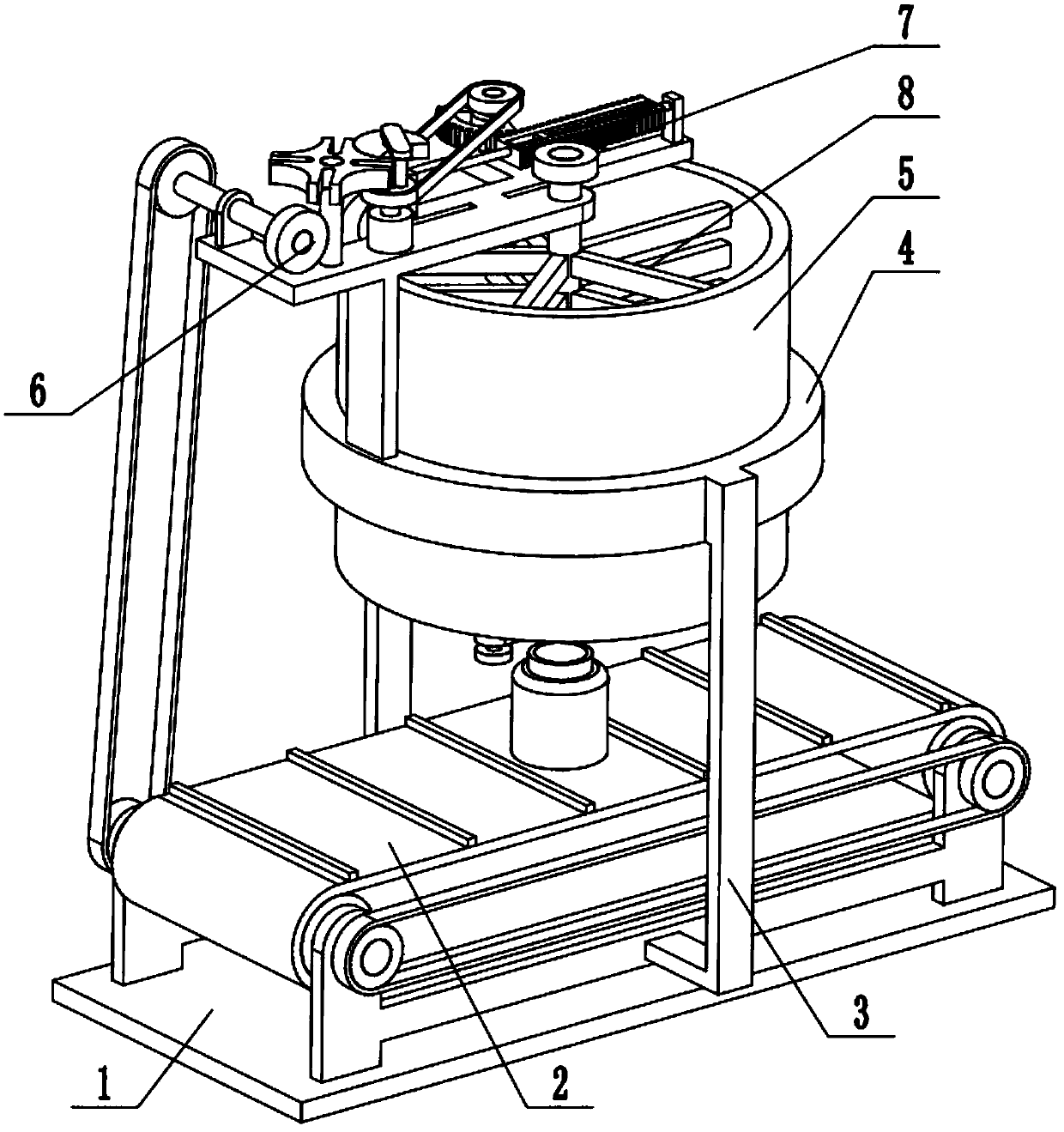
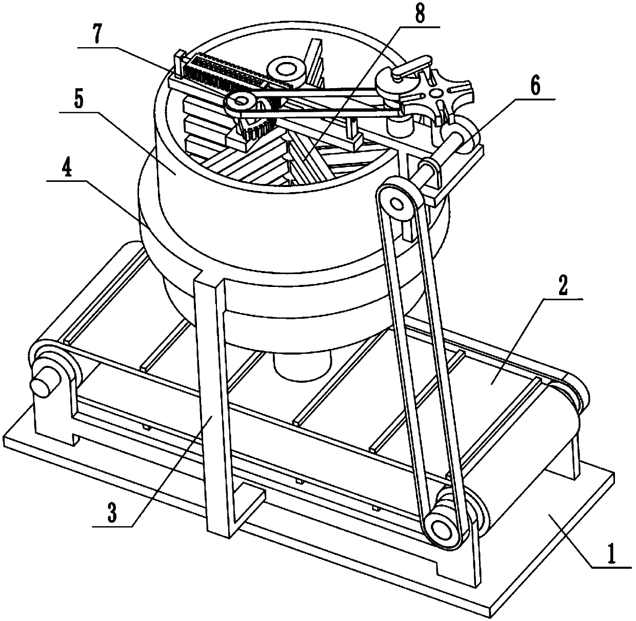
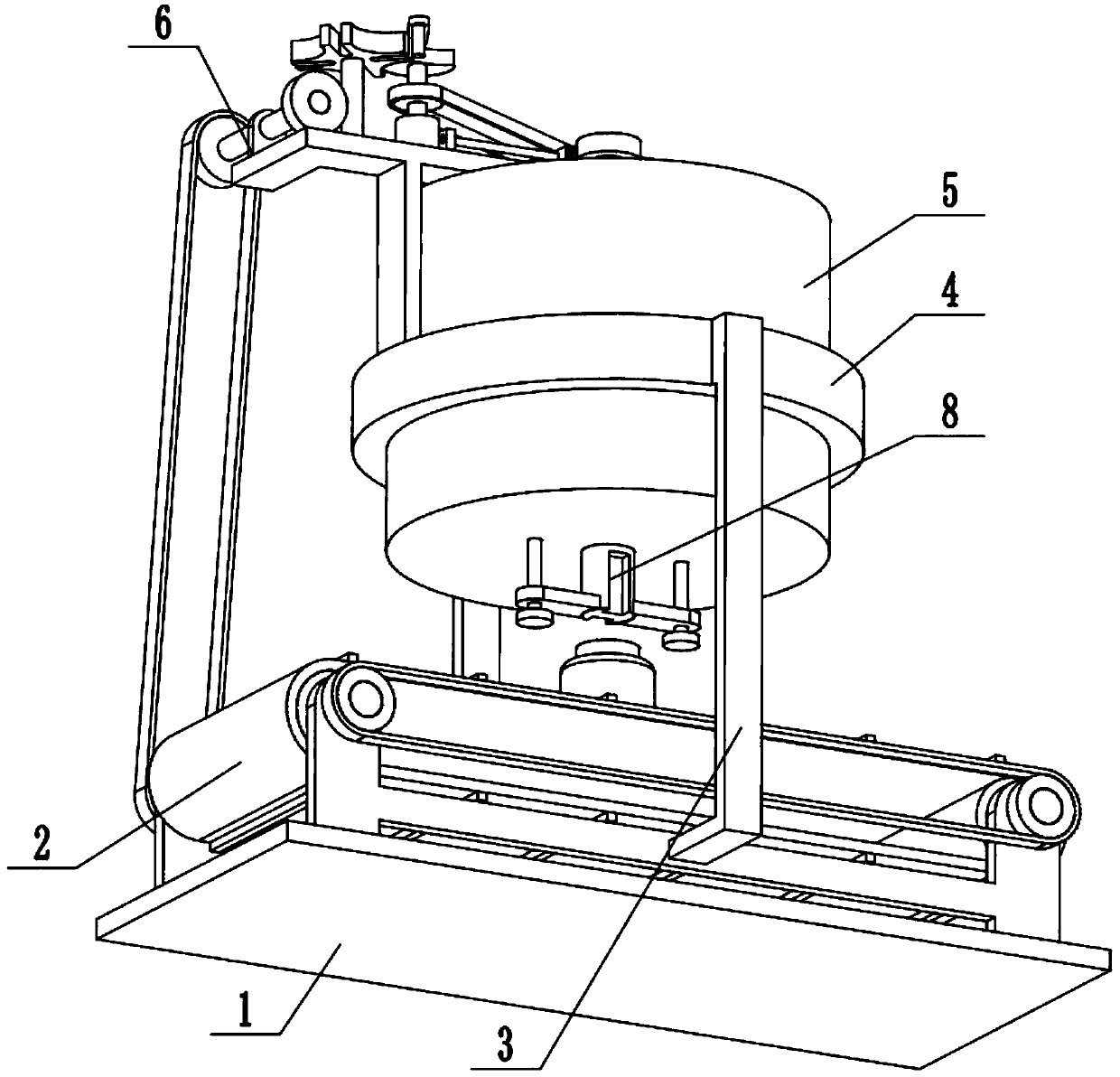
[0026] Combine below Figure 1-9Describe this embodiment, a shower gel filling system, including a bottom plate 1, a transmission assembly 2, a C-shaped connecting rod 3, a ring-shaped fixing seat 4, a shower gel storage box 5, a power transmission wheel assembly 6, and an intermittent discharge control mechanism 7 and an intermittent discharge mechanism 8, the transmission assembly 2 is fixedly connected to the bottom plate 1, two C-shaped connecting rods 3 are symmetrically fixedly connected to the front and rear ends of the transmission assembly 2, and the ring-shaped fixing seat 4 is fixedly connected to the two The upper end of the C-shaped connecting rod 3, the shower gel storage box 5 is fixedly connected to the inner side of the ring-shaped fixed seat 4, the power transmission wheel assembly 6 is fixedly connected to one end of the ring-shaped fixed seat 4, and the power transmission wheel assembly 6 and the transmission assembly 2 pass through Belt drive connection, t...

specific Embodiment approach 2

[0027] Combine below Figure 1-9 To illustrate this embodiment, the conveying assembly 2 includes a first roller shaft 2-1, a second roller shaft 2-2, a left leg 2-3, a right leg 2-4, a roller 2-5, Conveyor belt body 2-6, transverse baffle plate 2-7, connecting plate 2-8, linkage pulley Ⅰ 2-9, transmission pulley 2-10 and linkage pulley Ⅱ 2-11; two parts of the first roller shaft 2-1 The two ends of the second roller shaft 2-2 are respectively connected to the two right legs 2-4 through the bearings on the two right legs 2-4 through the bearings with seats. The left outrigger 2-3 and the two right outriggers 2-4 are all fixedly connected on the bottom plate 1; the middle ends of the first roller shaft 2-1 and the second roller shaft 2-2 are respectively fixedly connected with a roller The cylinder 2-5 and the two rollers 2-5 are connected through the transmission belt body 2-6, and the transmission belt body 2-6 is evenly provided with a plurality of transverse baffles 2-7; t...

specific Embodiment approach 3

[0028] Combine below Figure 1-9 To illustrate this embodiment, the power transmission wheel assembly 6 includes an L-shaped seat plate 6-1, a vertical plate 6-2, a motor 6-3, a driving shaft 6-4, a driving pulley 6-5, and an intermittent disc 6- 6. Intermittent wheel 6-7, worm screw 6-8, worm wheel 6-9, driving pulley 6-10, belt wheel rotating shaft 6-11 and shaft frame plate 6-12; L-shaped seat plate 6-1 passes through vertical plate 6 -2 is fixedly connected to the left end of the ring-shaped fixed seat 4, the motor 6-3 is fixedly connected to the L-shaped seat plate 6-1 through the motor frame, and the output shaft of the motor 6-3 is connected to the driving shaft 6-4 through a coupling, The intermittent disc 6-6 and the driving pulley 6-5 are fixedly connected to the driving shaft 6-4 sequentially from top to bottom, and the driving pulley 6-5 is connected with the intermittent discharge control mechanism 7 through a belt drive; the intermittent pulley 6 -6 is in cleara...


PUM


Abstract

The invention relates to the technical field of pouring and more particularly relates to a shower gel pouring system. A transmission assembly is fixedly connected to a bottom plate. Two C-shaped connecting rods are symmetrically and fixedly connected to the front end and the rear end of the transmission assembly. A ring-shaped fixing seat is fixedly connected to the upper ends of the two C-shapedconnecting rods. A shower gel storage box is fixedly connected to the inner side of the ring-shaped fixing seat. A power transmission wheel assembly is fixedly connected to one end of the ring-shapedfixing seat. The power transmission wheel assembly is in transmission connection with the transmission assembly through a belt. An intermittent discharging control mechanism is fixedly connected to the power transmission wheel assembly. By means of the shower gel pouring system, raw material liquid can be stirred evenly, raw material fluidity is improved, meanwhile, a heating function is achieved,and the phenomenon that the air temperature is low in winter, and consequently the shower gel fluidity is poor, and the pouring quality is affected is avoided; and pouring is stopped automatically after pouring is conducted by certain mass, continuous, uniform and quantitative distribution pouring is achieved on shower gel, the labor intensity of workers is lowered, and the work efficiency is improved.

Description

technical field [0001] The invention relates to the technical field of filling, in particular to a shower gel filling system. Background technique [0002] Filling machines are widely used in the food industry, beverage industry, and daily chemical industry. The filling machine has always been the solid backing of the beverage market, especially in the modern market, people's requirements for product quality are increasing day by day, market demand is expanding, and enterprises require efficient and automated production. Under such circumstances, the filling machine is even more It has become a hot filling equipment. In the actual production process, the filling of liquids is generally carried out manually, and the requirements for operators are relatively high. Especially when quantitative filling is required, the error of manual filling is large, and the work efficiency is low. meet production needs. Contents of the invention [0003] The purpose of the present invent...

Claims


Application Information

Patent Timeline
Patent Type & Authority Applications(China)
IPC IPC(8): B67C3/24B67C3/26B67C3/22
CPCB67C3/22B67C3/24B67C3/26
Inventor 闫岩
Owner 广州汇芬生物科技有限公司
Why Eureka
Try Eureka