Refrigeration equipment and heat conduction part thereof

A technology of refrigeration equipment and heat conduction parts, applied in the field of preparation, can solve the problems of increasing the flow resistance of the refrigerant in the tube, hindering the full development of the refrigerant in the tube, and not being able to change the D-shaped tube evaporator, so as to improve refrigeration efficiency, reduce energy consumption, The effect of high cooling efficiency

Inactive Publication Date: 2019-04-30
HEFEI HUALING CO LTD +2
View PDF5 Cites 0 Cited by
  • Summary
  • Abstract
  • Description
  • Claims
  • Application Information

AI Technical Summary

Problems solved by technology

However, the shape of the D-shaped tube evaporator hinders the full development of the refrigerant in the tube, which greatly increases the flow resistance of the refrigerant in the tube and increases the energy consumption
Moreo...

Method used


Image

  • Refrigeration equipment and heat conduction part thereof
  • Refrigeration equipment and heat conduction part thereof
  • Refrigeration equipment and heat conduction part thereof

Examples


Embodiment Construction

[0026] Embodiments of the invention are described in detail below, examples of which are illustrated in the accompanying drawings. The embodiments described below by referring to the figures are exemplary and are intended to explain the present invention and should not be construed as limiting the present invention.

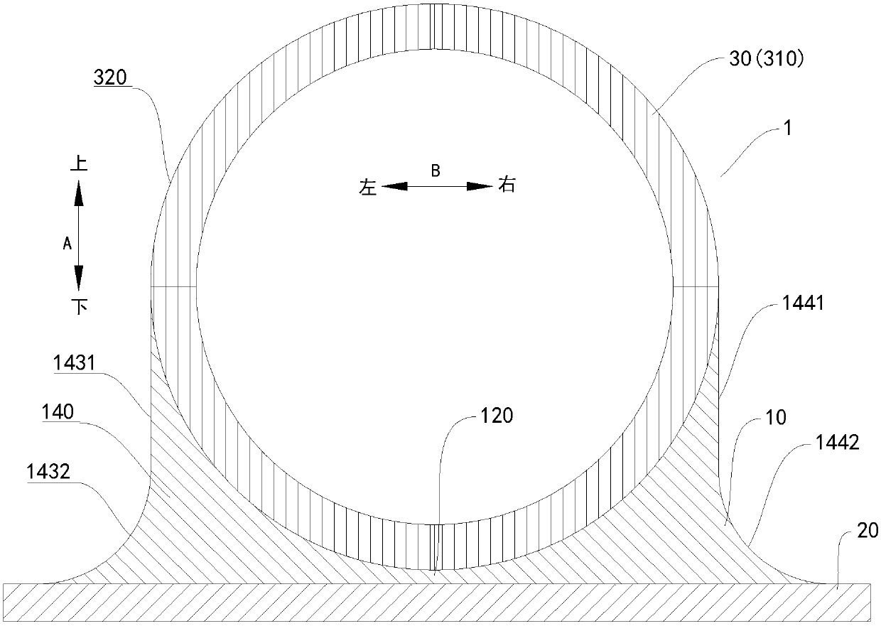
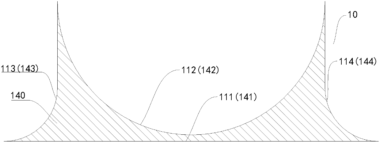
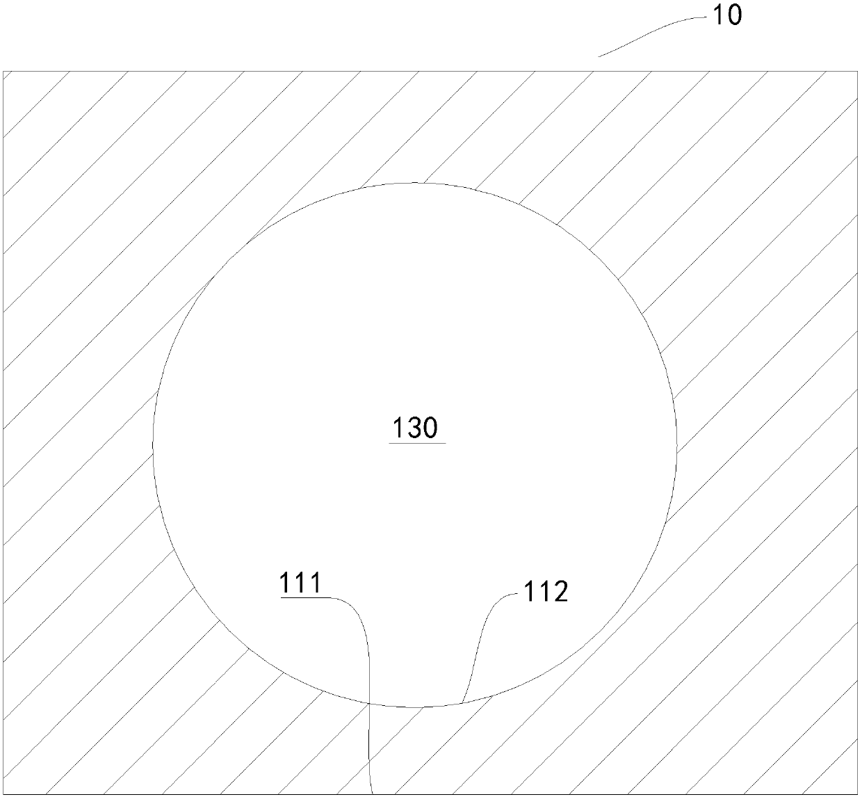
[0027] A refrigeration device 1 according to an embodiment of the present invention will be described below with reference to the drawings. like Figure 1-Figure 3 As shown, the refrigeration device 1 according to the embodiment of the present invention includes an inner container 20 , an evaporator 30 and a heat conducting element 10 .

[0028] The evaporator 30 includes an evaporation tube 310 . The heat conducting element 10 has a first surface 111 and a second surface 112 opposite to each other, at least a part of the first surface 111 is a plane, and at least a part of the second surface 112 is a curved surface. Wherein, at least a part of the first surfa...


PUM

PropertyMeasurementUnit
Central angleaaaaaaaaaa

Abstract

The invention discloses refrigeration equipment and a heat conduction part thereof. The refrigeration equipment includes an inner container, an evaporator which includes an evaporation tube, and the heat conduction part. The heat conduction part is provided with a first surface and a second surface which are opposite to each other. At least one part of the first surface is a plane. At least one part of the second surface is a curved surface. The at least one part of the first surface is in contact with the inner container, and the at least one part of the second surface is in contact with theevaporation tube. The refrigeration equipment of the embodiments of the invention has the advantages of high refrigeration effect, low energy consumption, uniform refrigeration chamber temperature, good fresh-keeping effect, low manufacturing cost, simple assembly process and the like.

Description

technical field [0001] The invention relates to the field of preparation, in particular to refrigeration equipment, and also to a heat conducting part of the refrigeration equipment. Background technique [0002] There are two types of coiled tube evaporators: [0003] The cross-section of the first type of coiled tube evaporator is circular. The disadvantage of this coiled tube evaporator is that it is in line contact with the inner tank, the contact area is small, and the heat transfer efficiency is low. [0004] The second type of coiled tube evaporator is a D-shaped tube evaporator, and the D-shaped tube evaporator is in surface contact with the inner tank, and the heat transfer efficiency is higher than that of the first type of coiled tube evaporator. However, the shape of the D-shaped tube evaporator hinders the full development of the refrigerant in the tube, greatly increases the flow resistance of the refrigerant in the tube, and increases energy consumption. Mor...

Claims


Application Information

Patent Timeline
IPC IPC(8): F25B39/02
CPCF25B39/02
Inventor 刘文信
Owner HEFEI HUALING CO LTD
Why Eureka
Try Eureka