
Textile defect detection device based on machine vision

A machine vision and detection device technology, applied in measurement devices, instruments, scientific instruments, etc., can solve the problems of blocking defects, large detection errors, affecting the detection effect, etc., to improve the accuracy, improve the dust removal effect, and improve the detection effect. Effect

Inactive Publication Date: 2019-04-30
杭州锦绣工坊工艺品有限公司
View PDF0 Cites 5 Cited by
  • Summary
  • Abstract
  • Description
  • Claims
  • Application Information

AI Technical Summary

Problems solved by technology

[0005] The purpose of the present invention is to provide a textile defect detection device based on machine vision to solve the problems in the above-mentioned background technology that dust impurities cause large detection errors and folds block the defects, which affects the detection effect

Method used

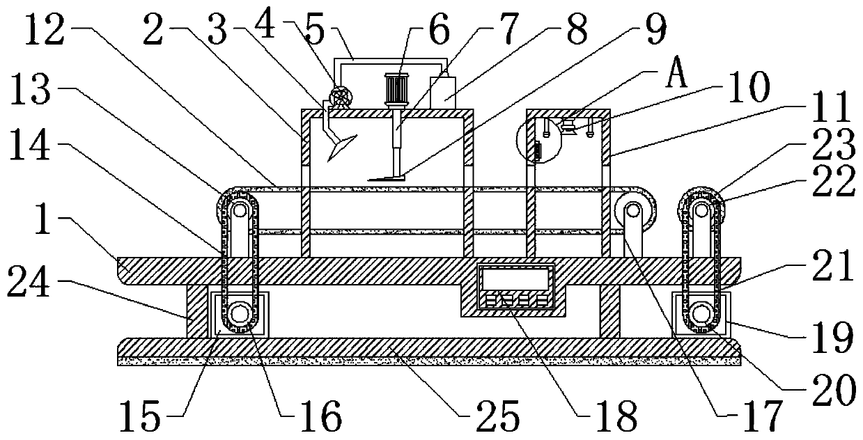
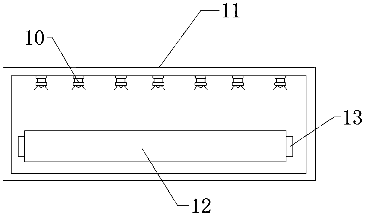
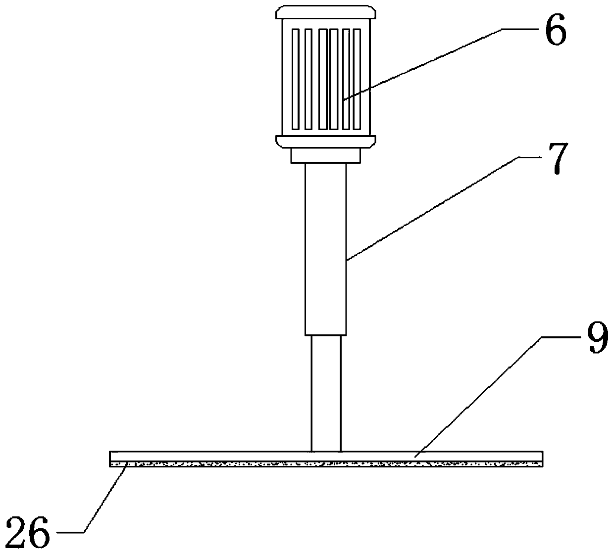

Image

  • Textile defect detection device based on machine vision
  • Textile defect detection device based on machine vision
  • Textile defect detection device based on machine vision

Examples


Embodiment Construction

[0020] The technical solutions in the embodiments of the present invention will be clearly and completely described below in conjunction with the accompanying drawings in the embodiments of the present invention. Obviously, the described embodiments are only some of the embodiments of the present invention, not all of them. Based on The embodiments of the present invention and all other embodiments obtained by persons of ordinary skill in the art without making creative efforts belong to the protection scope of the present invention.

[0021] In the present invention: the model of the wireless image transmitting board is T5, and the model of the industrial camera is WP-U500 / WP-U500M.

[0022] see Figure 1-4 , the present invention provides a technical solution: a textile defect detection device based on machine vision, including a workbench 1, a dust removal chamber 2, an exhaust pipe 3, a fan 4, a dust pipe 5, a cylinder 6, a piston rod 7, a storage Dust box 8, pressure pla...


PUM


Abstract

The invention discloses a textile defect detection device based on machine vision. The device comprises a workbench; a guide rail is arranged at the top of the workbench; a speed reducing motor, a rotating shaft and a storage battery are arranged in the workbench; the top end of the rotating shaft penetrates through the upper portion of the interior of the workbench and is fixedly provided with abase plate. The cosmetic storage and display device convenient to use is provided with a guide rail, a connecting rod, a rolling wheel and a first spring; in the starting and operating process of thespeed reducing motor, vibration generated by the speed reducing motor can be transmitted to the first spring through the fixing plate; the first spring is used for buffering and eliminating vibrationforce generated by vibration due to own specific contraction and composite force, so that the device is more stable in the operating process; and meanwhile, the speed reducing motor rotates to drive the connecting rod and the rolling wheel to slide in the guide rail, and a supporting rod and the rolling wheel play a role in supporting the center of the device in the process of rotation of the speed reducing motor, so that the problem that the gravity center is unstable is solved to a great extent.

Description

technical field [0001] The invention relates to the technical field of textile defect detection, in particular to a textile defect detection device based on machine vision. Background technique [0002] Textiles are a product made of textile fibers through processing and weaving, and are divided into two categories: woven fabrics and knitted fabrics. [0003] Defects: Refers to the spots or small defects that should not exist on the fabric. From fiber raw materials to the final manufacturing of finished fabrics, it needs to go through spinning, weaving, printing and dyeing and other processes, and in each process, it needs to go through a continuous process. (Process) can only be completed. [0004] Existing machine vision-based textile defect detection devices have relatively large errors. When there are non-defective dust impurities on the surface of textiles, they will also be identified as defects by the device detection, resulting in large detection errors. For textil...

Claims


Application Information

Patent Timeline
IPC IPC(8): G01N21/898G01N21/01
CPCG01N21/8983G01N21/01
Inventor 劳以军操时英
Owner 杭州锦绣工坊工艺品有限公司
Learn More