Anti-reflux joint

An anti-reflux and interface technology, applied in the direction of connecting tubes, instruments introduced into the body, catheters, etc., can solve the problems of blood return in the infusion pipeline, increase the pain, and increase the blocking rate of the puncture needle, and achieve the effect of smooth infusion and drainage.

Pending Publication Date: 2019-05-03
张霞
View PDF6 Cites 1 Cited by
  • Summary
  • Abstract
  • Description
  • Claims
  • Application Information

AI Technical Summary

Problems solved by technology

However, due to the shortage of clinical nurses, it is impossible to take full care of patients during the infusion process. Due to various reasons, the blood in the infusion line returns. If the liquid level is too low, the drop is less than the blood pressure of the human body, and blood backflow occurs; some patients are not allowed to measure blood pressure at the infusion side, and the cuff pressure will cause blood backflow during pressure measurement; blood flow back
However, blood backflow easily increases the rate of puncture needle blockage, and patients need to re-puncture to increase pain, increase medical expenses, and increase the workload of nursing staff.
[0004] Urinary catheter drainage uses the principle of gravity, but due to the lack of clinical knowledge of patients and incorrect care by medical staff, it is easy to place the drainage tube higher than the level of the bladder, resulting in the reflux of urine drained from the urinary catheter and urine bag , increasing the rate of urinary tract infection in patients

Method used


Image

  • Anti-reflux joint
  • Anti-reflux joint
  • Anti-reflux joint

Examples


Embodiment Construction

[0025] The following will clearly and completely describe the technical solutions in the embodiments of the present invention with reference to the accompanying drawings in the embodiments of the present invention. Obviously, the described embodiments are only some, not all, embodiments of the present invention. Based on the embodiments of the present invention, all other embodiments obtained by persons of ordinary skill in the art without making creative efforts belong to the protection scope of the present invention.

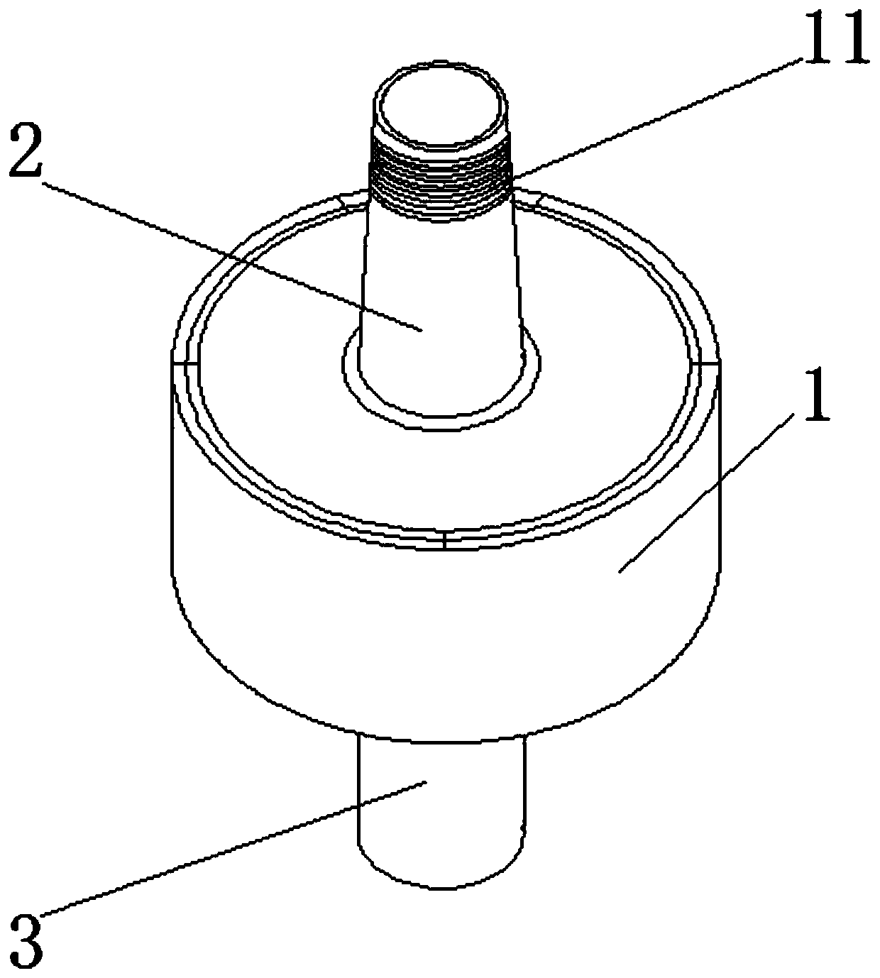
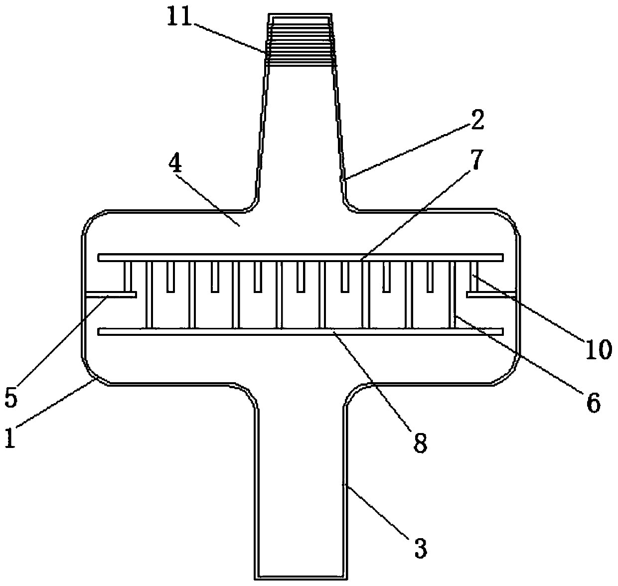
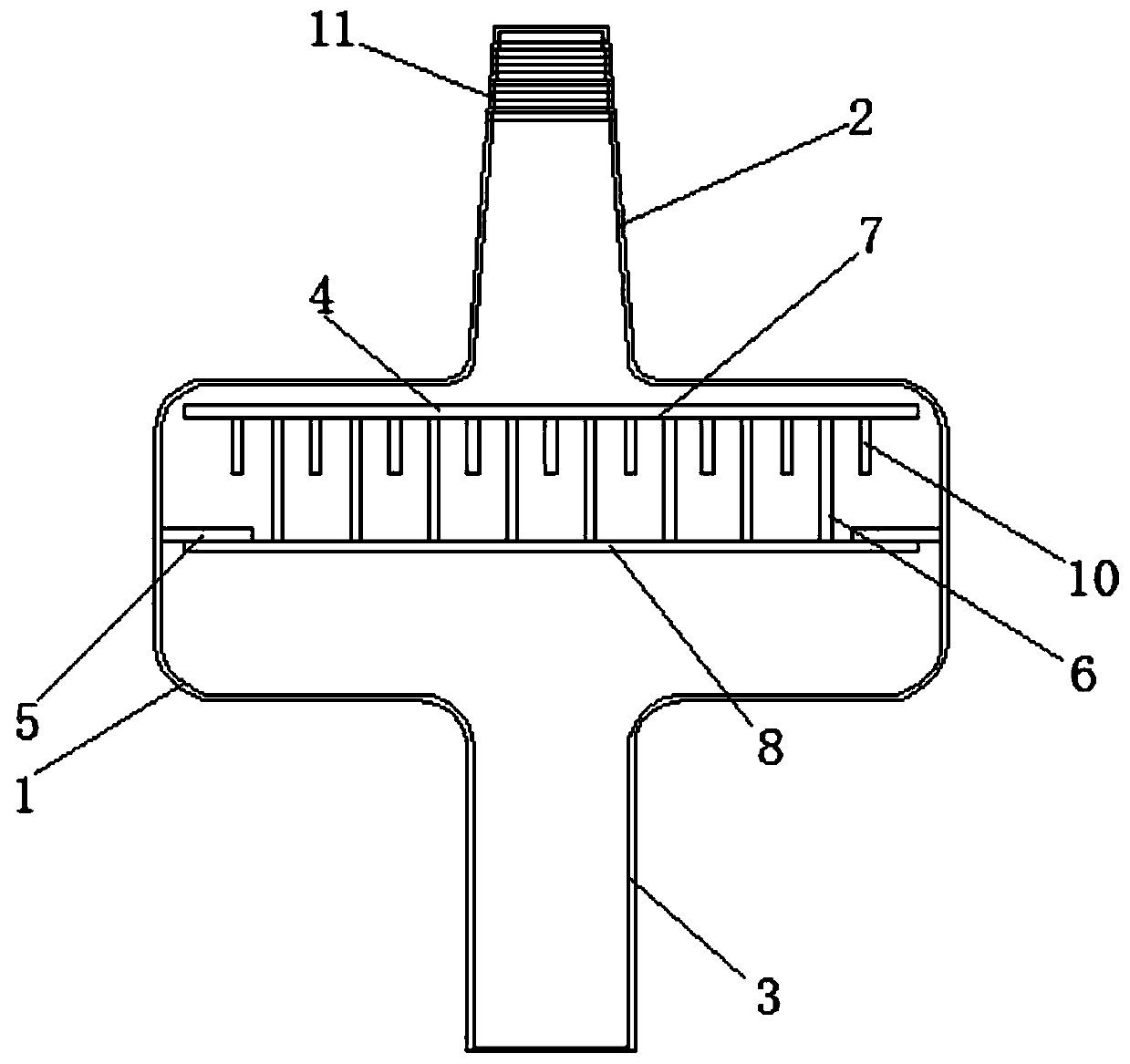
[0026] see Figure 1-5 , the present invention provides a technical solution: an anti-reflux joint, including an anti-reflux body 1, a first interface 2 is provided at the top center of the anti-reflux body 1, and a bottom center of the anti-reflux body 1 is provided with The second interface 3, the inner wall of the anti-backflow main body 1 is provided with an annular buoy valve baffle 5, the inside of the anti-reflux main body 1 is provided with a cavity 4,...


PUM


Abstract

The invention discloses an anti-reflux joint. The anti-reflux joint comprises an anti-reflux main body; a first interface is arranged at the center of the top of the anti-reflux main body; a second interface is arranged at the center of the bottom of the anti-reflux main body; an annular buoy valve baffle is arranged on an inner wall of the anti-reflux main body; a buoy valve is arranged, in movable connection, inside the anti-reflux main body; and the buoy valve is composed of a buoy valve upper baffle, a buoy valve lower baffle, a plurality of hollowed water flow lattices and a plurality ofanti-reflux bulge columns. When the anti-reflux joint is in use, the buoy valve moves downwards when liquid flows from the first interface to the second interface, so that, the liquid can flow into the hollowed cylindrical buoy valve through the hollowed water flow lattices between the buoy valve and the inner wall of the anti-reflux main body; and then, the liquid flows out through the hollowed water flow lattices, and flows to the second interface so as to achieve smooth infusion and drainage. When liquid flows from the second interface to the first interface, the buoy valve is pushed by theliquid so as to allow tight contact of the buoy valve lower baffle with the annular buoy valve baffle; and thus, flow of the liquid from the second interface to the first interface is prevented, thereby achieving the anti-reflux effect.

Description

technical field [0001] The invention relates to the technical field of medical joints, in particular to an anti-reflux joint. Background technique [0002] At present, there are two main problems caused by fluid reflux clinically. One is that blood reflux in the infusion line is prone to occur due to intravenous infusion; [0003] Intravenous infusion is to use the principle of atmospheric pressure and hydrostatic pressure to inject liquid into the human body. However, due to the shortage of clinical nurses, it is impossible to take full care of patients during the infusion process. Due to various reasons, the blood in the infusion line returns. If the liquid level is too low, the drop is less than the blood pressure of the human body, and blood backflow occurs; some patients are not allowed to measure blood pressure at the infusion side, and the cuff pressure will cause blood backflow during pressure measurement; blood backflow. And the backflow of blood easily increases...

Claims


Application Information

Patent Timeline
Patent Type & Authority Applications(China)
IPC IPC(8): A61M39/10A61M39/24A61M5/14A61M25/00
Inventor 张霞
Owner 张霞
Why Eureka
Try Eureka