Sizing cutting device for thick plate continuous casting machine and method for improving sizing accuracy
A technology of fixed-length cutting and continuous casting machine, which is applied in the field of iron and steel metallurgy, can solve the problems of decreased weighing accuracy and uncertain weight of cast slabs, and achieves the effect of reducing fluctuation and improving the accuracy of fixed-length.
- Summary
- Abstract
- Description
- Claims
- Application Information
AI Technical Summary
Problems solved by technology
Method used
Image
Examples
Embodiment 1
[0058] A method for improving sizing accuracy, comprising the steps of:
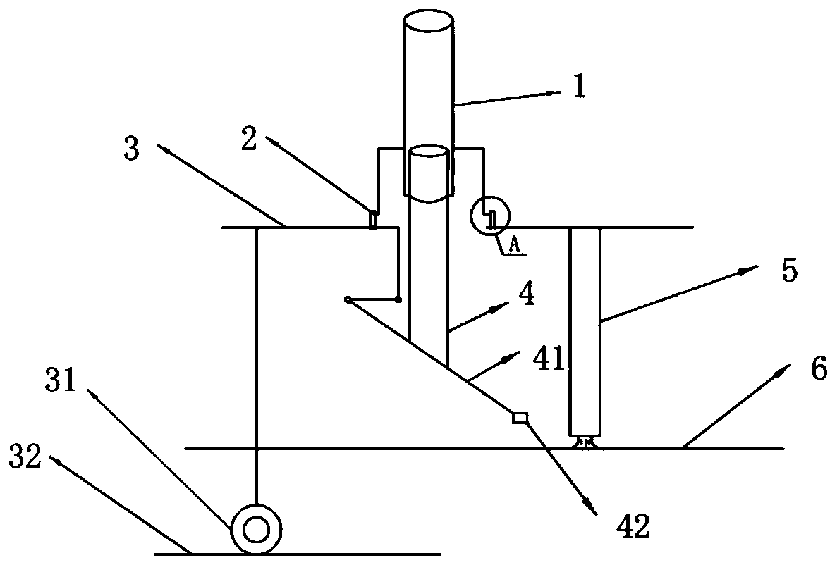
[0059] (a) Use the device described in Embodiment 1 to cut the casting slab 6 to a fixed length, so that the distance between the pressing rod ram 41 and the casting slab 6 is kept constant, so that the pressing rod ram 41 can move from receiving the pressing signal to The time difference for compacting the strand 6 remains constant.
[0060] Specifically, the distance between the pneumatic cylinder 1 and the cutting trolley 3 can be adjusted by adjusting the height of the pad 2, and the height h of the pad 2 1 With slab thickness h 2 The difference between them is a fixed value a, and pads 2 of different heights are used for slabs 6 of thickness (200-300) mm, so that the distance between the pressing head 41 of the compression rod and the slab 6 remains constant. That is to say, a taller spacer 2 is used for the thick casting slab 6 to increase the height of the air cylinder 1, and the height of the p...
Embodiment 2
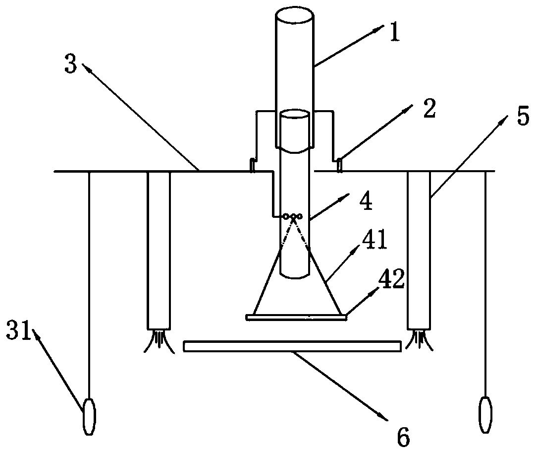
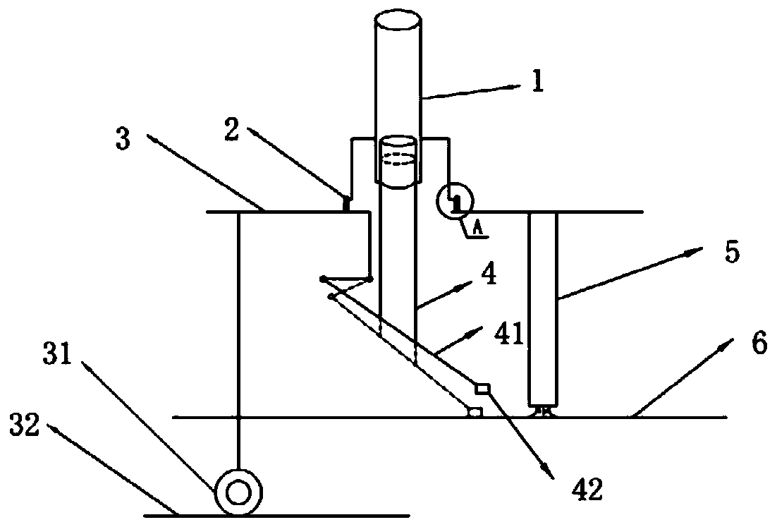
[0070] Such as Figure 1-7 Shown is the cut-to-length cutting device for a thick plate continuous casting machine shown in this embodiment, including a flame cutting trolley 3 and a track 32 for the longitudinal movement of the flame cutting trolley 3, and the flame cutting trolley 3 is moved and assembled on the track 32. The flame cutting trolley 3 is provided with a crossbeam spanning the cast slab, and the center of the crossbeam is provided with a pressing device, and the pressing device includes a pneumatic cylinder 1, a pressing rod 4 connected to the bottom of the pneumatic cylinder 1, and a pressing head of the pressing rod 41. The pneumatic cylinder 1 is connected with the flame cutting trolley 3 through the pad 2, the pneumatic cylinder 1 is connected with the compression rod head 41 through the compression rod 4, and the pneumatic cylinder 1 can drive the compression rod 4 to move up and down; One end of the pressing head of the pressing rod is connected to the fla...
example
[0088] Such as Figure 1 to Figure 7 As shown, using the method described in Example 1 and the device described in Example 2, for the casting slabs 6 with thicknesses of 200mm, 250mm, and 300mm, spacers 2 with heights of 150mm, 200mm, and 250mm were used respectively, so that the compression rod pressed The distance between the head 41 and the slab 6 is kept constant. Before the pre-compression, the distance between the thicker steel plate 42 at the lower part of the compression rod head and the casting slab is 210mm. After the pre-compaction, the distance between the compression rod pressure head The distance between the thicker steel plate 42 at the bottom and the slab is 30mm.
[0089] The cut-to-length system used in this example is provided by Shanghai Xinzhong Metallurgical Equipment Factory, and the product model is BGB. The thickness of the compression rod pressing head 41 is 10mm.
[0090] The angle between the upper plane of the compression rod pressing head 41 and...
PUM
| Property | Measurement | Unit |
|---|---|---|
| height | aaaaa | aaaaa |
| thickness | aaaaa | aaaaa |
| length | aaaaa | aaaaa |
Abstract
Description
Claims
Application Information
 - R&D
- Intellectual Property
- Life Sciences
- Materials
- Tech Scout
- Unparalleled Data Quality
- Higher Quality Content
- 60% Fewer Hallucinations
Browse by: Latest US Patents, China's latest patents, Technical Efficacy Thesaurus, Application Domain, Technology Topic, Popular Technical Reports.
© 2025 PatSnap. All rights reserved.Legal|Privacy policy|Modern Slavery Act Transparency Statement|Sitemap|About US| Contact US: help@patsnap.com


