An automatic assembly equipment for air-conditioning accessories and its process

A technology of automatic assembly and accessories, which is applied in the field of air-conditioning materials, can solve problems such as wasting time, and achieve the effects of convenient welding work, high precision, and cost-saving output

Inactive Publication Date: 2021-03-05
南通秋祥信息科技有限公司
View PDF9 Cites 0 Cited by
  • Summary
  • Abstract
  • Description
  • Claims
  • Application Information

AI Technical Summary

Problems solved by technology

[0005] The purpose of the present invention is to address the deficiencies of the prior art, by setting a turning mechanism, the assembled air-conditioning accessories can be accurately and automatically matched and placed on the inverted assembly, and the vertical turning and positioning of the assembled product can be completed during the process of transporting to the welding station , so as to solve the technical problem of manually aligning and assembling the air-conditioning accessories and their end covers during the manual welding of the air-conditioning accessories, which wastes time

Method used


Image

  • An automatic assembly equipment for air-conditioning accessories and its process
  • An automatic assembly equipment for air-conditioning accessories and its process
  • An automatic assembly equipment for air-conditioning accessories and its process

Examples


Embodiment 1

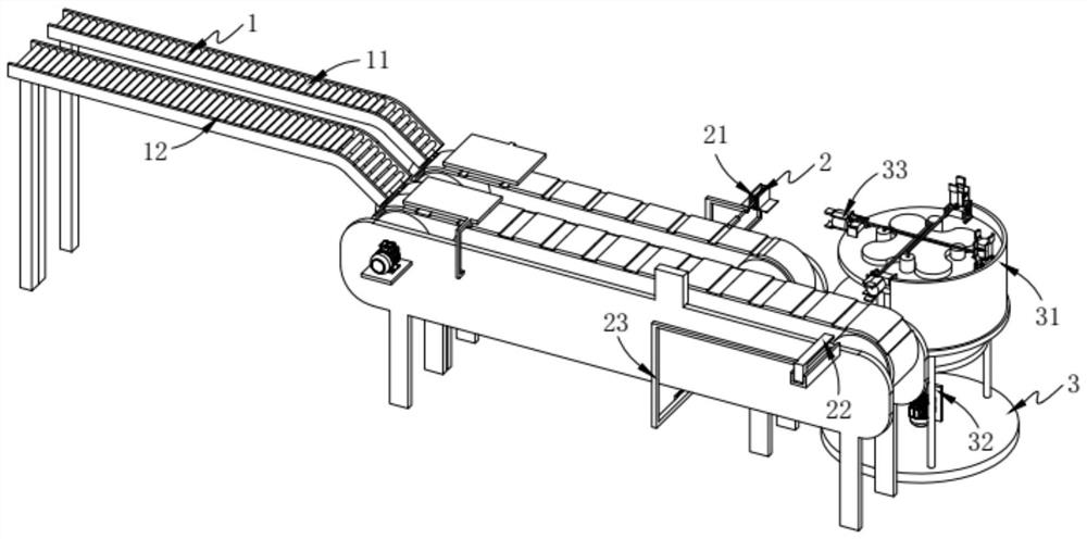
[0079] Such as figure 1 As shown, an automatic assembly equipment for air-conditioning accessories, including:

[0080] An upper loading mechanism 1, the upper loading mechanism 1 includes a first conveying assembly 11 and a second conveying assembly 12 arranged on one side of the first conveying assembly 11;

[0081] Forming mechanism 2, the forming mechanism 2 includes a drive assembly 21 fixedly arranged at the output end of the first conveying assembly 11, a discharge assembly 22 arranged at the output end of the second conveying assembly 12, and one end connected to the drive assembly 21 And the steering assembly 23 whose other end is connected to the discharge assembly 22; and

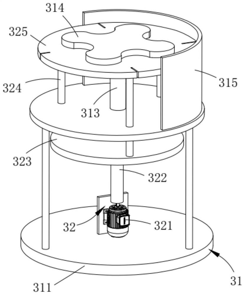
[0082] Turning mechanism 3, the turning mechanism 3 includes a support assembly 31 arranged at the output end of the first conveying assembly 11, a circular assembly 32 arranged on the support assembly 31 and a plurality of arrays along the circumferential direction of the circular assembly 32 ...

Embodiment 2

[0140] Such as Figure 10 As shown, the components that are the same as or corresponding to those in the first embodiment are marked with the corresponding reference numerals in the first embodiment. For the sake of simplicity, only the differences from the first embodiment will be described below. The difference between this embodiment two and embodiment one is:

[0141] further, such as Figure 10 As shown, the steering assembly 23 includes:

[0142] A forward component 231, the forward component 231 includes a connecting rod a232 with one end fixedly connected to the telescopic end of the cylinder 212 and a rack a233 fixedly connected with the connecting rod a232;

[0143] A retreat assembly 234, the retreat assembly 234 includes a connecting rod b235 fixedly connected to the sliding rod 222 at one end and a rack b236 fixedly connected to the connecting rod b235; and

[0144] A gear 237, the gear 237 is rotatably disposed on the bottom of the frame b1221 and the gear 237...


PUM


Abstract

The invention relates to an automatic assembly equipment for air-conditioning accessories and its technology, comprising: an upper loading mechanism, the upper loading mechanism includes a first conveying assembly and a second conveying assembly arranged on one side of the first conveying assembly; a forming mechanism, the The forming mechanism includes a driving assembly fixedly arranged at the output end of the first conveying assembly, a discharge assembly arranged at the output end of the second conveying assembly, and a steering assembly connected at one end to the drive assembly and at the other end to the discharge assembly. assembly; and an overturning mechanism, the overturning mechanism includes a support assembly arranged at the output end of the first conveying assembly, a circular assembly rotatably arranged on the support assembly, and several groups of inverted assemblies arrayed along the circumferential direction of the circular assembly The present invention solves the technical problem that the air-conditioning accessories and their end covers need to be manually aligned and assembled during the manual welding of the air-conditioning accessories, which wastes time.

Description

technical field [0001] The invention relates to the technical field of air-conditioning parts, in particular to an automatic assembly equipment for air-conditioning parts and a process thereof. Background technique [0002] At present, the parts of the air conditioner used in the air conditioner need to be connected and sealed by welding. The traditional welding table or welding fixture for the workpiece of the welding machine for automotive air conditioner parts is a fixed structure. [0003] Patent No. CN104043889B discloses a welding machine for automotive air-conditioning accessories, including a welding platform mechanism for placing air-conditioning accessories, a welding torch, a welding material pipe, a welding material fixing and adjusting mechanism, a welding torch and welding material adjusting mechanism, and a cylinder push-pull mechanism. The hand wheel height adjustment mechanism on the frame, the welding station mechanism is set on the frame and located on the...

Claims


Application Information

Patent Timeline
Patent Type & Authority Patents(China)
IPC IPC(8): B23K31/02B23K37/047
Inventor 梁金雷
Owner 南通秋祥信息科技有限公司
Why Eureka
Try Eureka