
Precision processing machine for micro holes

A technology of micro-hole processing and processing machines, which is applied in the direction of metal processing machinery parts, metal processing equipment, manufacturing tools, etc., can solve the problems of reducing the working efficiency of micro-hole processing machines, increasing the cost of object processing, and adjusting and fixing more time. It achieves the effect of convenient installation, fixing, disassembly and replacement, reducing the time for adjustment and fixing, and facilitating disassembly, maintenance and replacement

Inactive Publication Date: 2019-05-03
方占萍
View PDF2 Cites 2 Cited by
  • Summary
  • Abstract
  • Description
  • Claims
  • Application Information

AI Technical Summary

Problems solved by technology

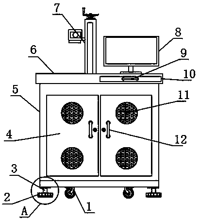
[0004] The purpose of the present invention is to provide a precision micro-hole processing machine to solve the problem that the existing micro-hole processing machine in the above background technology will produce slight vibration when in use, and the long-term vibration will cause the micro-hole processing machine to be on the ground. Sliding, so that the micro-hole processing of the object being processed fails, increasing the cost of object processing, and it takes more time to adjust and fix after the micro-hole processing machine moves, and the anti-skid pad at the bottom of the micro-hole processing machine is damaged by friction and is inconvenient to disassemble and replace , the problem of reducing the working efficiency of the micro-hole processing machine

Method used


Image

  • Precision processing machine for micro holes
  • Precision processing machine for micro holes
  • Precision processing machine for micro holes

Examples


Embodiment Construction

[0024] The following will clearly and completely describe the technical solutions in the embodiments of the present invention with reference to the accompanying drawings in the embodiments of the present invention. Obviously, the described embodiments are only some, not all, embodiments of the present invention. Based on the embodiments of the present invention, all other embodiments obtained by persons of ordinary skill in the art without making creative efforts belong to the protection scope of the present invention.

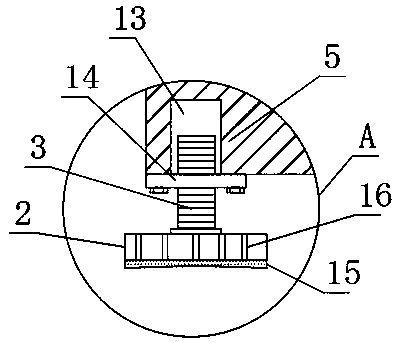
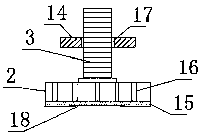
[0025] see figure 1 , figure 2 , image 3 , Figure 4 , Figure 5 and Figure 6 , the present invention provides a technical solution: a precision microhole processing machine, including a processing machine main body 5 and a moving mechanism provided on the lower surface of the processing machine main body 5, a fixing mechanism is provided at the bottom of the processing machine main body 5, and the fixing mechanism includes an anti-slip mat 2. Screw ro...


PUM


Abstract

The invention discloses a precision processing machine for micro holes. The processing machine includes a main processing machine body and a moving mechanism arranged on the lower surface of the mainprocessing machine body, wherein a fixed mechanism is arranged at the bottom end of the main processing machine body and includes a slide-proof pad, screws, a first thread groove, a reinforcing plate,an elastic suction cup, slide-proof protrusions, a threaded hole and a groove; the screws are symmetrically and fixedly arranged at the four corners of the lower surface of the main processing machine body; and the groove is formed in the lower surface of the elastic suction cup, so that the elastic suction cup is adsorbed on the ground through the groove, the firmness of the slide-proof pad on the ground is increased, and the main processing machine body is prevented from sliding on the ground during work. Through the slide-proof protrusions, the friction of the surface of the slide-proof pad is increased, so that the hands of workers are prevented from slipping when the slide-proof pad is rotated, and it is convenient for the workers to rotate the slide-proof pad and disassemble and replace the screws; and after the main processing machine body is moved, the time for adjusting and fixing is shortened; the installation efficiency of the workers is improved; and the work efficiency ofthe main processing machine body is improved.

Description

technical field [0001] The invention belongs to the technical field of microhole processing machines, and in particular relates to a precision microhole processing machine. Background technique [0002] Micro-hole processing is an important processing procedure that accounts for a large proportion in mechanical processing. According to statistics, micro-hole processing accounts for about one-third of the total amount of mechanical processing and one-quarter of the machining time. With the development of science and technology and industrial production such as aviation, electronics, machinery, instrumentation, chemical fiber, automatic control and medical equipment, the application of micropores is becoming more and more extensive. [0003] The existing micro-hole processing machine will produce slight vibration when in use, and the long-term vibration will cause the micro-hole processing machine to slide on the ground, so that the micro-hole processing of the object being pr...

Claims


Application Information

Patent Timeline
IPC IPC(8): B23Q1/72B23Q11/00
Inventor 方占萍冯黎成陈其虎程明杰甄亮张振伟张康张永婷
Owner 方占萍
Learn More