
Automatic lateral sponge supporting synchronous operation device

A synchronous operation and automatic technology, applied in the direction of metal processing, etc., can solve the problems of reducing cutting accuracy, affecting cutting accuracy, slippage of sponge and conveyor belt, etc., and achieving the effect of avoiding the reduction of cutting accuracy and having strong versatility

Pending Publication Date: 2019-05-03
南通恒康数控机械股份有限公司
View PDF1 Cites 8 Cited by
  • Summary
  • Abstract
  • Description
  • Claims
  • Application Information

AI Technical Summary

Problems solved by technology

[0004] Although the above-mentioned structure realizes the righting of the sponge, it only arranges a pair of righting conveyor belts at the feed end or the discharge end to correct the position of the passing sponge, but when the sponge is separated from the righting conveyor belt, Before cutting, there is still a certain distance to be transported, and in the process of transporting the sponge on the conveyor belt, slipping between the sponge and the conveyor belt is prone to occur, which affects the cutting accuracy, resulting in a decrease in cutting accuracy. When cutting on the side, the cut side sponge is easy to separate from the sponge body, which affects the cutting accuracy of the side sponge

Method used


Image

  • Automatic lateral sponge supporting synchronous operation device
  • Automatic lateral sponge supporting synchronous operation device
  • Automatic lateral sponge supporting synchronous operation device

Examples


Embodiment Construction

[0022] The following examples can enable those skilled in the art to understand the present invention more comprehensively, but the present invention is not limited to the scope of the described examples.

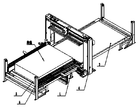
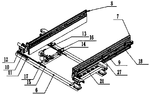
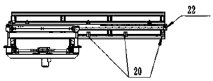
[0023] Such as Figure 1-Figure 5 Shown is an automatic lateral cotton-supporting synchronous operation device, the automatic lateral cotton-supporting synchronous operation device is installed on a sponge cutting machine, and the sponge cutting machine includes a conveying bracket 1, and a feed conveyor belt 2 is installed on the conveying bracket 1 , the discharge conveyor belt 3, and the feed conveyor belt 2 and the discharge conveyor belt 3 are driven by their respective drive motors to work, and the feed conveyor belt 2 and the discharge conveyor belt 3 are located on the conveyor bracket 1 A pair of vertically arranged guide rollers 5 are all set at the outlets of the outlets, and a gantry 4 is also arranged between the feed conveyor belt 2 and the discharge conveyor ...


PUM


Abstract

The invention relates to an automatic lateral sponge supporting synchronous operation device. The automatic lateral sponge supporting synchronous operation device comprises a pair of sponge supportingplates arranged on the two sides of a conveying support, the two sponge supporting plates are jointly matched to achieve clamping of a sponge, and the two sponge supporting plates are driven by a transverse moving mechanism to do reciprocated moving between a feeding conveying belt and a discharging conveying belt. The device has the advantages that the two sponge supporting plates are matched jointly to achieve clamping of the two sides of the sponge, through cooperation of the transverse moving mechanism, the sponge supporting plates can synchronously move in the conveying process of the feeding conveying belt, it is ensured that in the cutting whole process, sponge clamping is achieved, the phenomenon that due to slippage between the sponge and the conveying belts, the cutting precision is reduced is avoided, in addition, it is ensured that the cut side sponge is not separated from the sponge body, and the cutting precision of the side sponge is affected.

Description

technical field [0001] The invention relates to the field of sponge cutting, in particular to an automatic lateral cotton-supporting synchronous operation device. Background technique [0002] The sponge cutting machine is used to cut the sponge into pieces. When the gantry type sponge cutting machine is cutting the sponge, the sponge is moved to the gantry by the conveyor belt, and the sponge is cut by the blade on the gantry. During the movement of the sponge to the gantry on the conveyor belt, since the long axis of the sponge cannot be guaranteed to be perpendicular to the gantry, it is moved back and forth, and there is a certain position deviation, which affects the cutting accuracy. [0003] Therefore, in view of the above-mentioned phenomenon, a kind of sponge cutting machine guide righting device has just been mentioned in patent CN102794787A, and its innovation point is to include: a righting conveyor belt, and described righting conveyor belt is arranged on the sp...

Claims


Application Information

Patent Timeline
IPC IPC(8): B26D7/06B26D7/02
Inventor 倪张根吴晓宇吴鹏翔秦曹阳林长彬
Owner 南通恒康数控机械股份有限公司
Learn More