Display

A display and display panel technology, applied in instruments, light guides, optics, etc., can solve problems such as unfavorable heat dissipation

Inactive Publication Date: 2019-05-03
SHENZHEN FUTAIHONG PRECISION IND CO LTD +1
11 Cites 1 Cited by

AI-Extracted Technical Summary

Problems solved by technology

As a result, the heat source becomes more and more concentrated, and ...

Method used

[0022] It can be understood that, in this embodiment, the buffer member 23 directly adheres the heat dissipation member 21 to the reflective sheet 105 through its own viscosity, and is set corresponding to the light source 103. In this way, the point-shaped heat source generated by the light source 103 can be dissipated evenly without additional adhesive, which can effectively reduce the thickness of the display 100 and reduce its manufacturing cost. In addition, due to the micro-adhesive property of the buffer member 23 , the buffer member 23 is easily torn off from the backlight module 10 , so rework is easy. At the same time, the cushioning member 23 is an elastic soft material. Compared with pasting the foam layer on the heat dissipation member 21 and the reflective sheet 105 through adhesive, the bonding is smoother and does not generate air bubbles. Water ripples generated by the display 100 are a...

Abstract

The invention discloses a display. The display includes a backlight module and further includes a heat radiation module, wherein the heat radiation module includes a heat radiation member and a buffermember, the heat radiation member is a sheet-like heat radiation material, the heat radiation member is arranged at a lower surface of the backlight module, the buffer member is a flexible material with self viscosity and self elasticity, the buffer member is directly bonded on the heat radiation member through self viscosity to make the heat radiation member fixed on the backlight module. The display is advantaged in that the buffer member is directly bonded on the heat radiation member through self viscosity to make the heat radiation member fixed on the backlight module, the back glue is not utilized, thickness of the display can be effectively reduced, and cost is further reduced.

Application Domain

Optical light guidesNon-linear optics

Technology Topic

OptoelectronicsRadiation +2

Image

  • Display
  • Display
  • Display

Examples

  • Experimental program(1)

Example Embodiment

[0013] The technical solutions in the embodiments of the present invention will be clearly and completely described below in conjunction with the accompanying drawings in the embodiments of the present invention. Obviously, the described embodiments are only a part of the embodiments of the present invention, rather than all the embodiments. Based on the embodiments of the present invention, all other embodiments obtained by those of ordinary skill in the art without creative work shall fall within the protection scope of the present invention.
[0014] Unless otherwise defined, all technical and scientific terms used herein have the same meaning as commonly understood by those skilled in the technical field of the present invention. The terms used in the specification of the present invention herein are only for the purpose of describing specific embodiments, and are not intended to limit the present invention. The term "and/or" as used herein includes any and all combinations of one or more related listed items.
[0015] Hereinafter, some embodiments of the present invention will be described in detail with reference to the accompanying drawings. In the case of no conflict, the following embodiments and features in the embodiments can be combined with each other.
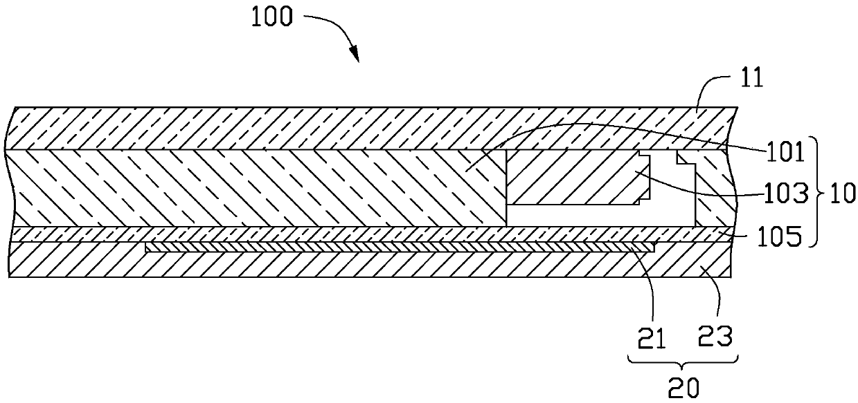
[0016] See figure 1 , The first preferred embodiment of the present invention provides a display 100. The display 100 may be a display screen of an electronic device such as a mobile phone, a computer, a TV, or a game console. The display 100 at least includes a display panel 11, a backlight module 10 and a heat dissipation module 20.
[0017] The display panel 11 may be a liquid crystal display panel. The backlight module 10 is disposed under the display panel 11. The backlight module 10 includes a light guide plate 101, a light source 103 and a reflective sheet 105. The light source 103 is arranged adjacent to the light guide plate 101. In this embodiment, the light source 103 is a point light source, such as a light emitting diode, so that the light source 103 generates a point heat source. The reflective sheet 105 is directly disposed on a surface of the light guide plate 101 away from the display panel 11.
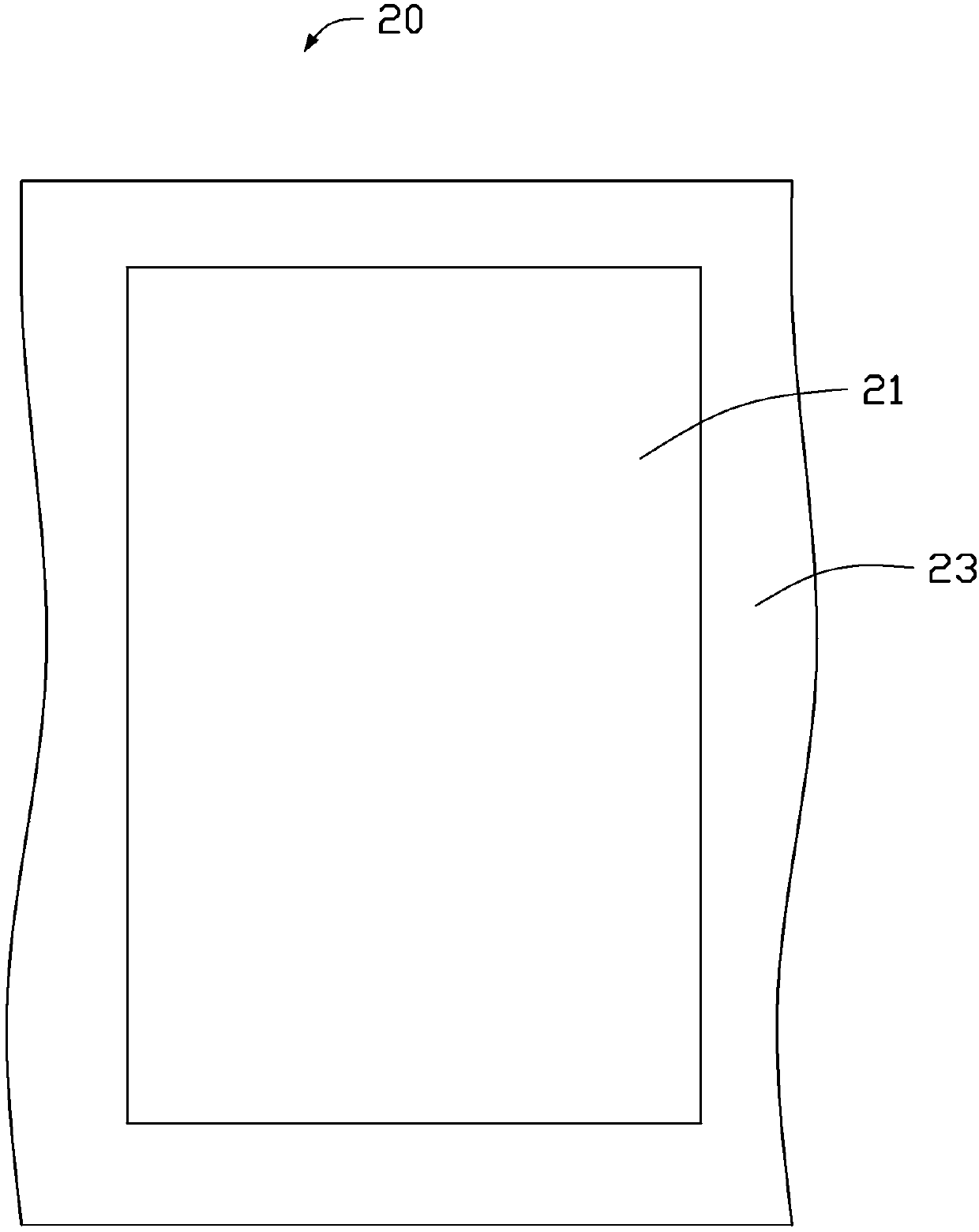
[0018] Please refer to figure 2 versus image 3 , figure 2 Is a schematic side view of the heat dissipation module 20, image 3 It is a schematic top view of the structure of the heat dissipation module 20. The heat dissipation module 20 includes a heat dissipation member 21 and a buffer member 23. The heat sink 21 is in the shape of a sheet, and the heat sink 21 is directly disposed on a surface of the reflective sheet 105 away from the light guide plate 101 and is disposed corresponding to the light source 103. In other words, the heat sink 21 is disposed on a side of the light source 103 away from the display panel 11. In this embodiment, the size of the heat sink 21 is smaller than the size of the reflective sheet 105. Of course, in other embodiments, the shape and size of the heat sink 21 can also be adjusted, as long as the area of ​​the heat sink 21 is larger than the area of ​​the light source 103.
[0019] In this embodiment, the heat dissipation member 21 is a sheet-shaped heat dissipation material. In this way, the heat sink 21 can diffuse the heat of the point heat source generated by the light source 103 to reduce the temperature, thereby solving the heat dissipation problem of the point heat source. In order to improve the heat dissipation performance of the heat dissipation element 21, the heat dissipation element 21 may be made of a heat dissipation material with good thermal conductivity such as graphite sheet or copper foil. Preferably, the thickness of the heat sink 21 ranges from 0.01 mm to 0.2 mm.
[0020] The buffer member 23 is generally sheet-shaped. The buffer member 23 is directly arranged on the surface of the heat sink 21 and the reflecting sheet 105 away from the light guide plate 101, or directly arranged on the surface of the heat sink 21 away from the reflecting sheet 105. In this embodiment, the shape and size of the buffer 23 roughly match the display panel 11. The buffer member 23 is made of a soft material with slight viscosity and elasticity. In this way, the buffer member 23 is adhered to the surface of the heat sink 21 and the reflective sheet 105 away from the light guide plate 101 through its adhesive effect. For example, when the size of the heat sink 21 is smaller than the size of the reflective sheet 105, the portion of the buffer member 23 corresponding to the heat sink 21 is directly attached to the surface of the heat sink 21 away from the light guide plate 101 The other parts are in direct contact with the surface of the reflective sheet 105 away from the light guide plate 101.
[0021] In this embodiment, the buffer member 23 is foam with a slight adhesiveness, such as acrylic foam. In this embodiment, the viscosity of the buffer member 23 ranges from 0.01N/25mm to 3N/25mm, that is, the force value required when the buffer member 23 with a standard length of 25mm is torn off.
[0022] It can be understood that, in this embodiment, the buffer member 23 directly adheres the heat dissipation member 21 to the reflective sheet 105 through its own viscosity, and is provided corresponding to the light source 103. In this way, the point-shaped heat source generated by the light source 103 can be uniformly dissipated without additional adhesive, which can effectively reduce the thickness of the display 100 and reduce its manufacturing cost. In addition, due to the inherent micro-viscosity characteristics of the buffer member 23, the buffer member 23 can be easily torn off from the backlight module 10, so heavy work is easy. At the same time, the cushioning member 23 is an elastic soft material. Compared with pasting a foam layer on the heat sink 21 and the reflective sheet 105 through a back glue, the bonding is more smooth and will not generate bubbles. The display 100 is prevented from generating water ripples, and the buffer effect is better. Secondly, the thermal expansion and contraction of the buffer member 23 is not obvious, so the thermal expansion of the reflective sheet 105 is not restricted.
[0023] See Figure 4 The second preferred embodiment of the present invention provides a display 200. The display 200 includes a display panel 11, a backlight module 10 and a heat dissipation module 20. It can be understood that the difference between the display 200 and the display 100 is that the display 200 further includes a metal frame 106. The metal frame 106 includes a bottom plate 107 and a side frame 108. The bottom plate 107 is directly disposed on a surface of the reflective sheet 105 away from the light guide plate 101. The side frame 108 is disposed on the periphery of the bottom plate 107, is substantially perpendicular to the bottom plate 107, and extends from the periphery of the bottom plate 107. In this way, the side frame 108 and the bottom plate 107 jointly enclose a receiving portion 109 for receiving the light guide plate 101, the light source 103 and the reflective sheet 105.
[0024] In this embodiment, the heat sink 21 is directly disposed on a surface of the bottom plate 107 away from the reflection sheet 105. The buffer member 23 is attached to the surface of the heat sink 21 and the bottom plate 107 away from the reflection sheet 105. For example, the part of the buffer member 23 corresponding to the heat sink 21 is directly in adhesive contact with the surface of the heat sink 21 away from the reflecting sheet 105, and the other part is directly in contact with the bottom plate 107 away from the reflecting sheet 105. Paste contacts on the surface.
[0025] Obviously, in the display 100/200 of the present invention, the buffer member 23 directly adheres the heat dissipation member 21 to the reflective sheet 105 or the metal frame 106 on a surface away from the light guide plate 101 through its own adhesiveness. There is no need to use adhesive, which can effectively reduce the thickness of the display 100/200 and reduce its cost. At the same time, the cushioning member 23 is an elastic soft material. Compared with attaching a foam layer to the backlight module 10 through a back glue, the attaching is smoother, no air bubbles are generated, and the The display 100/200 produces water ripples, and the cushioning effect is better.
[0026] The above embodiments are only used to illustrate the technical solutions of the present invention and not to limit them. Although the present invention has been described in detail with reference to the preferred embodiments, those of ordinary skill in the art should understand that the technical solutions of the present invention can be modified or equivalently replaced. , Without departing from the spirit and essence of the technical solution of the present invention.

PUM

no PUM

Description & Claims & Application Information

We can also present the details of the Description, Claims and Application information to help users get a comprehensive understanding of the technical details of the patent, such as background art, summary of invention, brief description of drawings, description of embodiments, and other original content. On the other hand, users can also determine the specific scope of protection of the technology through the list of claims; as well as understand the changes in the life cycle of the technology with the presentation of the patent timeline. Login to view more.
Why Eureka
Try Eureka