A double-frequency intelligent RFID tag chip and an electronic tag

A technology of RFID tags and chips, which is applied in the field of radio frequency identification, can solve problems such as increased chip costs, memory logic confusion, interference, etc., to achieve the effects of avoiding compatibility exceptions, reducing chip costs, and succinct judgment logic

Inactive Publication Date: 2019-05-03
WUHAN TIANYU JULIAN TECH CO LTD
View PDF7 Cites 3 Cited by
  • Summary
  • Abstract
  • Description
  • Claims
  • Application Information

AI Technical Summary

Problems solved by technology

With the continuous enrichment of RFID technology application scenarios, a single frequency band can no longer meet the needs of data collection and automatic identification, and a combination of multiple frequency bands is required for deployment
In order to make full use of the characteristics of the two frequency tags, most solutions are to package a high-frequency tag chip and a low-frequency or ultra-high-frequency electronic tag chip on a substrate, and still need to write data in the two tag chips It is very inconvenient to read and read; a few solutions are implemented with dual-frequency chips and shared memory. Although the effect of dual-frequency is achieved, the fault tolerance is poor. Frequency interference between each other; and common access to the same memory, read and write at the same time, memory logic confusion will occur; the front-end control circuits of each frequency band are independent, resulting in complex chip circuits and increasing chip costs

Method used


Image

  • A double-frequency intelligent RFID tag chip and an electronic tag
  • A double-frequency intelligent RFID tag chip and an electronic tag

Examples


Embodiment Construction

[0019] The following will clearly and completely describe the technical solutions in the embodiments of the present invention with reference to the accompanying drawings in the embodiments of the present invention. Obviously, the described embodiments are only a part of the present invention, not all embodiments. Based on the embodiments of the present invention, all other embodiments obtained by persons of ordinary skill in the art without making creative efforts belong to the protection scope of the present invention.

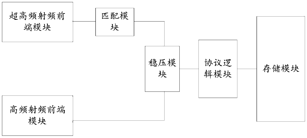
[0020] The dual-frequency intelligent RFID tag chip provided by the present invention includes a front-end sensing module, a matching module, a voltage stabilization module, a protocol control module, and a storage module. The other RF front-end module is electrically connected to the voltage stabilizing module through the matching module, and the voltage stabilizing module is electrically connected to the storage module through the protocol logic module.

[...


PUM


Abstract

The invention relates to a double-frequency intelligent RFID tag chip and an electronic tag. The RFID tag chip comprises a front-end induction module, a matching module, a voltage stabilization module, a protocol control module and a storage module, wherein the front-end sensing module comprises two radio frequency front-end modules with different frequency bands, one radio frequency front-end module is directly and electrically connected with the voltage stabilizing module, the other radio frequency front-end module is electrically connected with the voltage stabilizing module through the matching module, and the voltage stabilizing module is electrically connected with the storage module through the protocol logic module; the radio frequency front end module is used for obtaining energyfrom a reader-writer radiation field to form voltage; the matching module is used for enabling voltages on the two radio frequency front-end modules to be different; the voltage stabilizing module isused for stabilizing the voltages of the two radio frequency front-end modules so as to output a stabilized voltage; and the protocol logic module is used for adopting different protocols to access the storage module for different activation voltages. A low-frequency protocol, a high-frequency protocol or an ultrahigh-frequency protocol is controlled through voltage, and conflicts generated when multiple protocols are accessed at the same time are avoided.

Description

technical field [0001] The invention and the radio frequency identification field specifically relate to a dual-frequency intelligent RFID tag chip and an electronic tag. Background technique [0002] In the field of RFID radio frequency identification, according to the level of the carrier frequency, it can be divided into low frequency, high frequency or ultra high frequency, and use different communication protocols. Among them, the high-frequency identification technology with a working frequency of 13.56MHz is the most widely used, and is used for payment data exchange and identification of short-distance single items. Typical applications include: electronic tickets, electronic ID cards, electronic wallets, access control, etc., and related standards include: ISO14443, ISO15693, ISO18000-3 (13.56MHz), etc. The UHF radio frequency identification technology of 860Mhz-930Mhz is just the opposite. It is mainly used for long-distance identification of multiple items. The r...

Claims


Application Information

Patent Timeline
Patent Type & Authority Applications(China)
IPC IPC(8): G06K19/07G06K19/077
Inventor 何涛赵东董逢华杨斐霏
Owner WUHAN TIANYU JULIAN TECH CO LTD
Why Eureka
Try Eureka