A mobile edge computing unloading system and method based on a mobile agent
A technology of mobile agent and edge computing, which is applied in the field of mobile communication to achieve the effect of improving QoS, reducing management burden, and improving success rate
- Summary
- Abstract
- Description
- Claims
- Application Information
AI Technical Summary
Problems solved by technology
Method used
Image

Examples
Embodiment Construction
[0051] The technical solution of the present invention will be further described below in conjunction with the accompanying drawings.
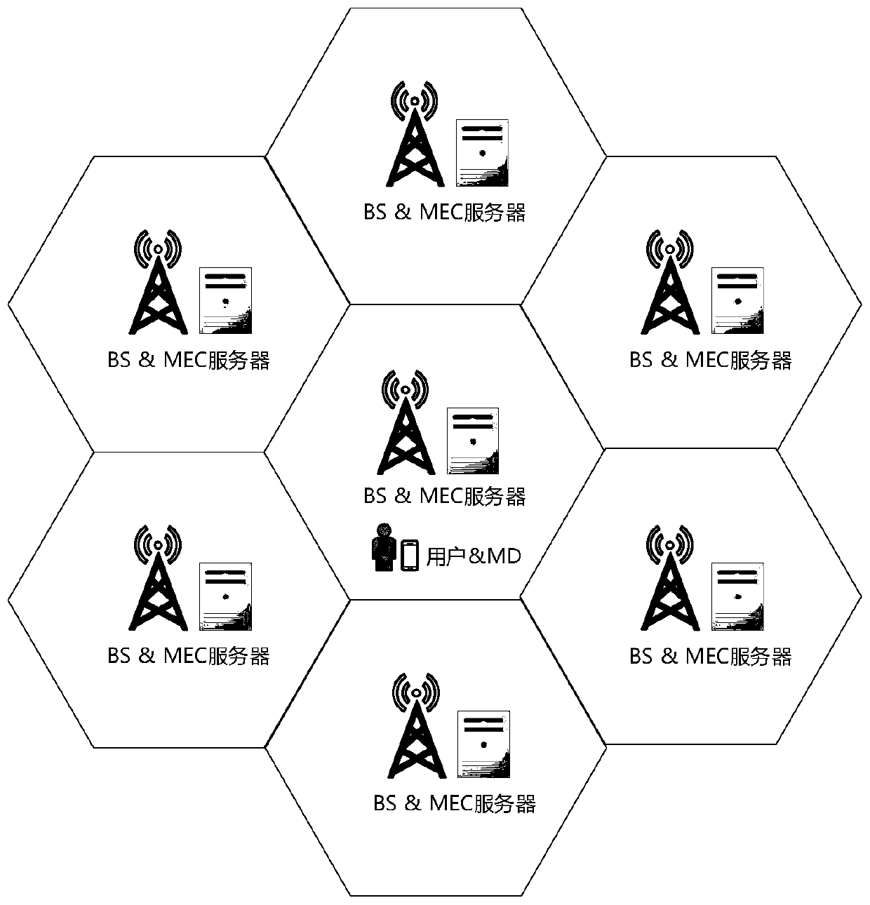
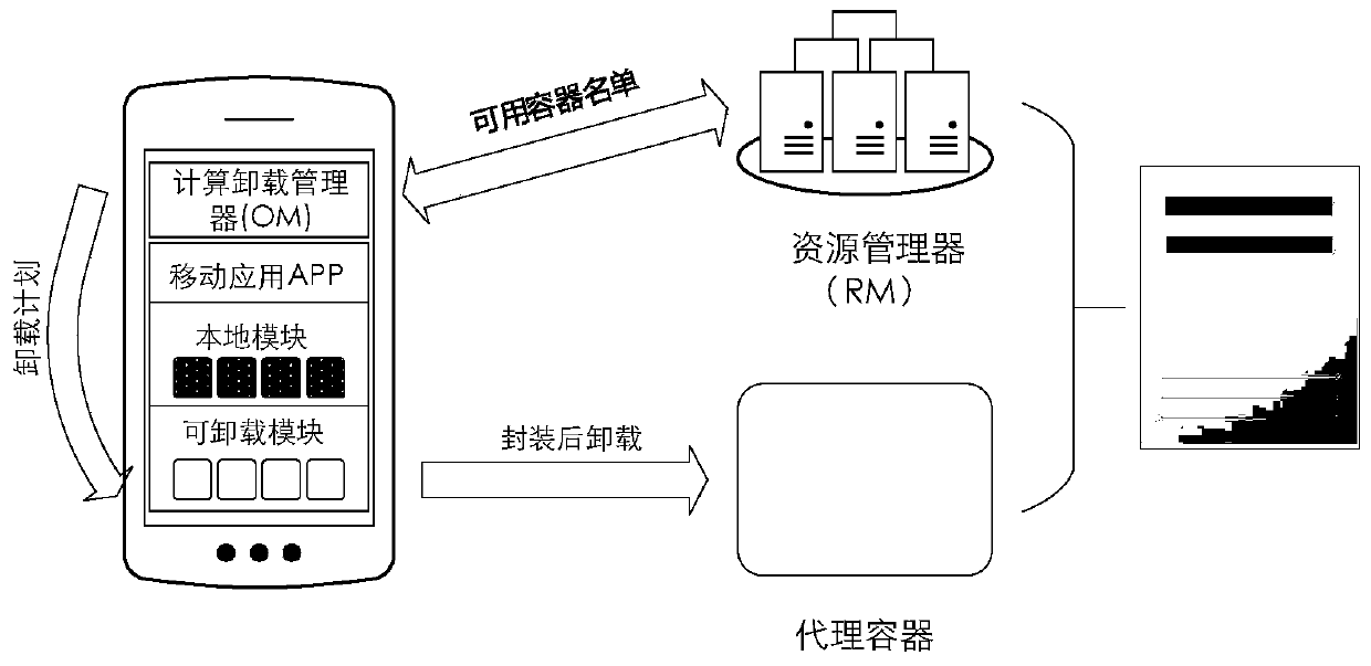
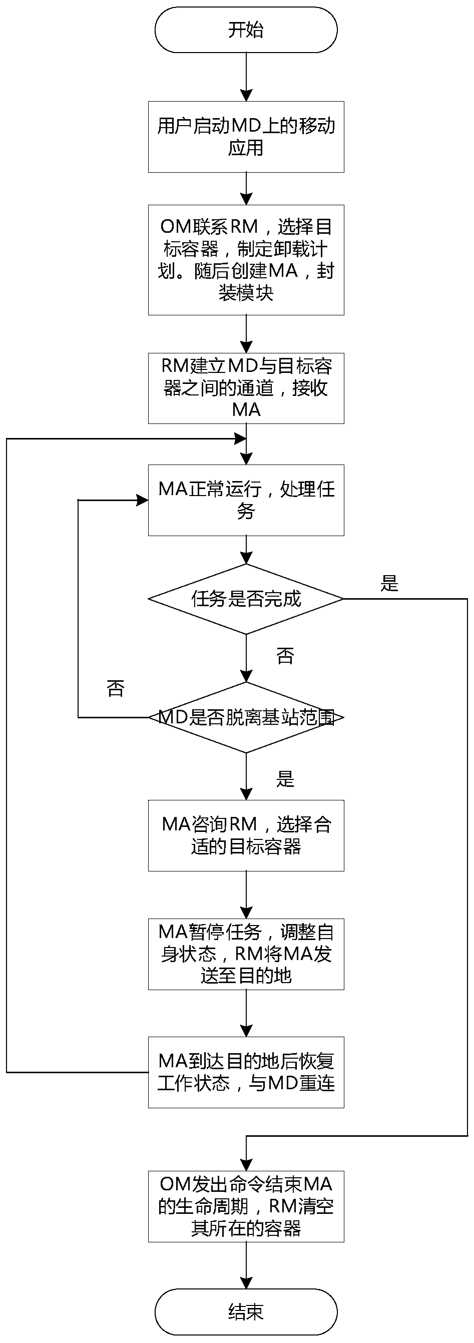
[0052] The computing offloading system model proposed by the present invention is based on a traditional cellular network model, and MEC servers are set up on a base station (Base Station, BS). refer to figure 1 and figure 2 , according to an embodiment, a mobile agent-based offloading system for mobile edge computing includes: an MEC server and a mobile device (Mobile Device, MD) held by a user, the MEC server is deployed on a BS, wherein the MEC server consists of two Partial composition: The first is the agent container, which is different from the container mentioned in the background. The agent container only provides a runtime environment for MA. Since the computing resources of the MEC server are far more abundant than those of the MD, the MEC server has the ability to run many proxy containers at the same time in order to provide se...
PUM
 Abstract
Description
Claims
Application Information