

A hull head drift flare-out slamming parallel computing method based on a three-dimensional model
A parallel computing and three-dimensional model technology, applied in complex mathematical operations, etc., can solve problems such as long calculation time, complex calculation principles, and reduced work efficiency, and achieve fast calculation speed, simple calculation principle, and intuitive and clear results.
- Summary
- Abstract
- Description
- Claims
- Application Information
AI Technical Summary
Problems solved by technology
Method used
Image

Examples
Embodiment 1
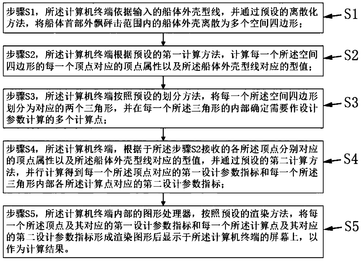
[0057] Please refer to figure 1 The first embodiment of the present invention provides a three-dimensional model-based parallel calculation method for hull bow slamming, which runs on a computer terminal and specifically includes the following steps:
[0058] Step S1, the computer terminal discretizes the hull shell within the slamming range of the bow of the hull into a plurality of spatial quadrilaterals according to the input hull shell shape line and through a preset discretization method;
[0059] A plurality of the space quadrilaterals and the hull shape lines constitute the hull bow slamming calculation database; the hull shape lines include waterlines and cross-section lines, and the hull shape lines can be processed through existing graphics Software processing forms.
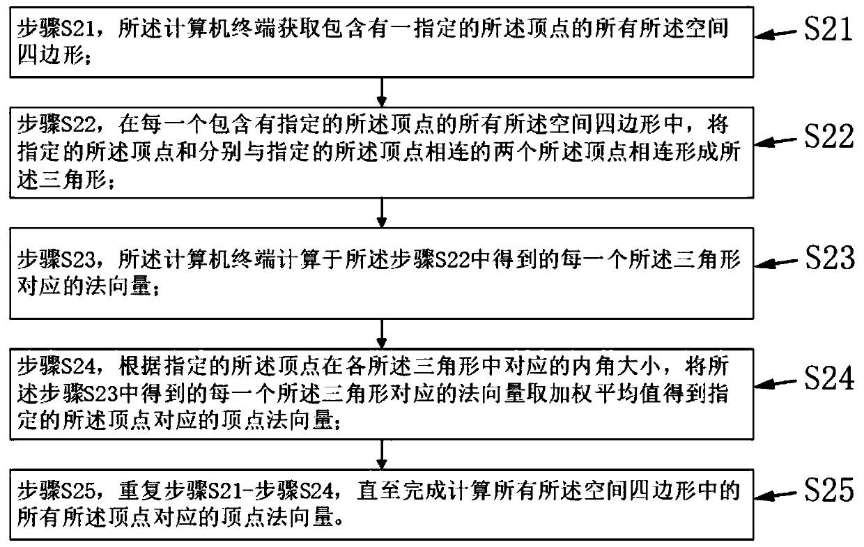
[0060] Step S2, the computer terminal calculates the vertex attributes corresponding to each vertex of each space quadrilateral and the model value corresponding to the hull shape line according to th...
Embodiment 2
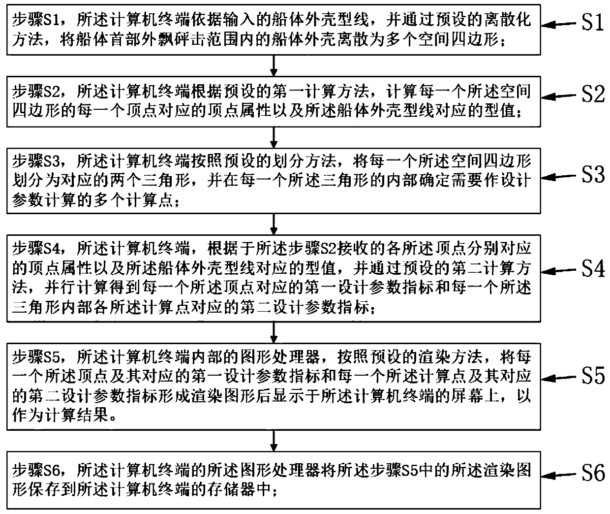
[0098] The difference between Embodiment 2 and Embodiment 1 is that please refer to figure 2 , the three-dimensional model-based parallel calculation method for hull bow slamming provided by Embodiment 2 of the present invention further includes:
[0099]Step S6, the graphics processor of the computer terminal saves the rendered graphics in the step S5 into a memory of the computer terminal;
[0100] The computer terminal also includes a user interaction module, the user interaction module is connected to the memory, and provided to the user when clicking any point in the rendered graphic on the screen of the computer terminal, the user interaction module can be obtained from the memory The first design parameter index corresponding to the selected arbitrary point or the vertex closest to the selected arbitrary point or the second design parameter index corresponding to the calculation point stored in , and displayed on the screen of the computer terminal.
[0101] Specific...
PUM
 Abstract
Description
Claims
Application Information