A centering method for the assembly process of stepped shaft and hole

A technology of stepped shafts and assembly holes, which is applied in the field of intelligent assembly, can solve the problems of not considering the fitting error and the unique characteristics of stepped shafts, etc., and achieve the effects of reducing algorithm complexity, ensuring accuracy, and high computing efficiency

Active Publication Date: 2021-05-07
NORTHWESTERN POLYTECHNICAL UNIV
View PDF10 Cites 2 Cited by
  • Summary
  • Abstract
  • Description
  • Claims
  • Application Information

AI Technical Summary

Problems solved by technology

[0004] After preliminary research and literature search, the current domestic research status on the shaft hole docking problem is as follows: Guangzhou Zhongchuan Wenchong Dock Co., Ltd. proposed a shaft and shaft hole alignment detection method and alignment detection device, the application publication number is CN109668530A, This method uses laser projection for axis fitting, but it is not applied in the assembly process; Zhangjiagang Chang'an University School of Automotive Engineering Han Yi's team proposed an automatic centering system for shaft hole assembly based on image processing, and the application publication number is CN 106204610A , this method does not consider the unique characteristics of the stepped shaft, and it only elaborates on the conventional shaft-hole fit, which has certain limitations; Cheng Yunyong's team from Northwestern Polytechnical University proposed an assembly alignment method based on machine vision monitoring, and the application publication number is CN 107617876A , using the stepped axis target to determine the assembly pose, this method uses circle fitting in the algorithm without considering the fitting error caused by the initial pose during the assembly process

Method used


Image

  • A centering method for the assembly process of stepped shaft and hole
  • A centering method for the assembly process of stepped shaft and hole
  • A centering method for the assembly process of stepped shaft and hole

Examples


Embodiment Construction

[0071] Embodiments of the present invention are described in detail below, and the embodiments are exemplary and intended to explain the present invention, but should not be construed as limiting the present invention.

[0072] The purpose of the present invention is to realize real-time monitoring and feedback on the alignment of the stepped shaft and the hole, and therefore proposes a centering method for the assembly process of the stepped shaft and the hole, which includes the following steps.

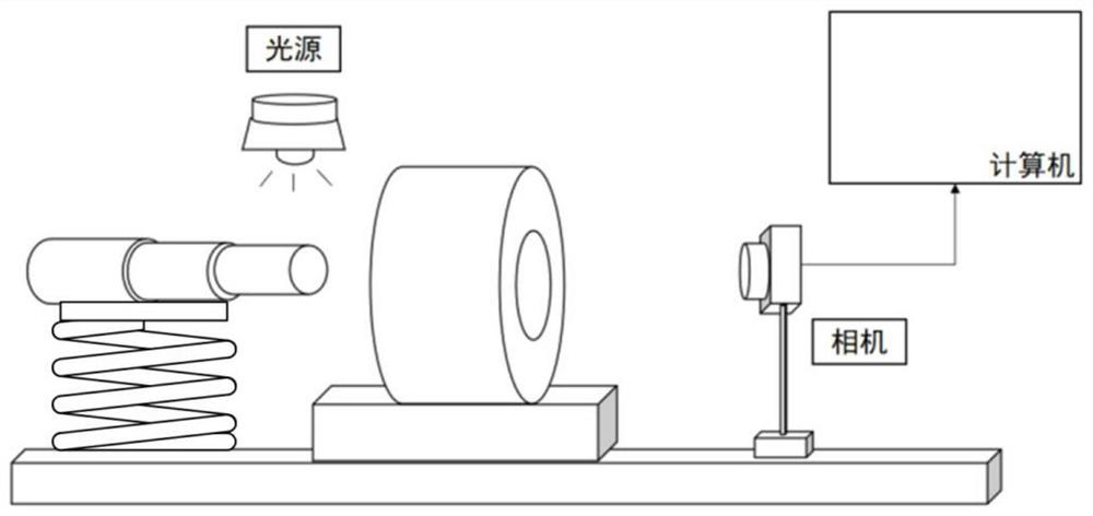
[0073] Step 1: Fix the calibrated industrial camera, fix the hole parts to be assembled in front of the camera, and install the light source to illuminate the through holes of the hole parts.

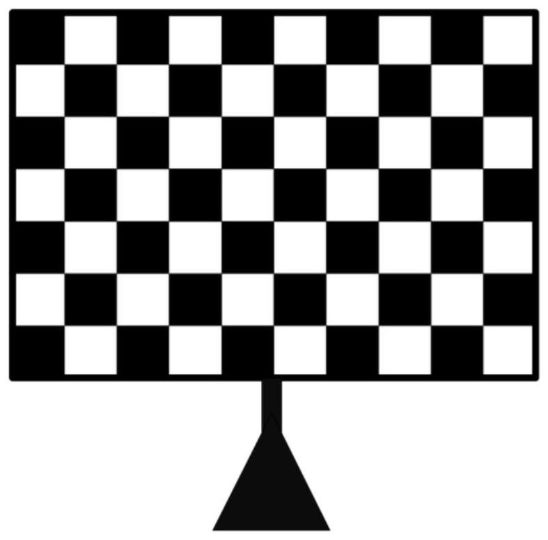
[0074] In the application of machine vision, in order to correct the distortion of the lens and determine the conversion relationship between the physical size and the pixel in reality, the industrial camera is calibrated using the chessboard pattern Ti-times CG-076-T. Such as figure 2 sho...


PUM


Abstract

The invention proposes a centering method for the assembly process of the stepped shaft and the hole. First, the image of the hole part is taken by a calibrated camera, and the centering deviation of the hole part is obtained by using the method of image recognition and ellipse fitting; The center deviation adjusts the position of the hole parts to be assembled until the axis of the through hole in the hole parts coincides with the axis of the camera, and fixes the position of the hole parts and the camera at this time; The image of the end face, and use the method of image recognition and ellipse fitting to get the fitting circle center of the small diameter end face of the stepped shaft and the fitting circle center coordinates of the middle diameter end face of the stepped shaft, connect the two circle centers and calculate the coordinates of the midpoint of the connection, using The coordinates of the midpoint are compared with the axis coordinates of the hole parts to adjust the pose of the stepped shaft to be assembled, and realize the centering monitoring of the stepped shaft and the hole. The invention realizes real-time monitoring and feedback of the alignment between the stepped shaft and the hole based on machine vision.

Description

technical field [0001] The invention belongs to the technical field of intelligent assembly, and in particular relates to a centering method for the assembly process of a stepped shaft and a hole. Background technique [0002] The main function of the stepped shaft is to use the shoulders with different radial dimensions to limit the movement of the parts on the shaft to position and install the parts. It is characterized by high manufacturing precision and small fit clearance. In the manufacturing fields of aviation, aerospace, automobiles and ships, the assembly of stepped shaft and hole parts is very common. With the continuous improvement of assembly requirements, the assembly accuracy of the stepped shaft and the hole has been paid more attention. Under the initial conditions, the hole and the stepped shaft are separated, and the centering deviation will inevitably occur during the centering process. Excessive deviation may cause bumps between the end faces of the st...

Claims


Application Information

Patent Timeline
Patent Type & Authority Patents(China)
IPC IPC(8): G01B11/27G06T7/00G06T7/70G06T7/13G06T7/60
CPCG01B11/27G06T7/0004G06T7/60G06T2207/10004G06T2207/30164G06T7/13G06T7/70
Inventor 莫蓉王琳璇王展孙惠斌常智勇
Owner NORTHWESTERN POLYTECHNICAL UNIV
Why Eureka
Try Eureka