
Circuit overcurrent protection device and method

A technology of overcurrent protection and circuit, which is applied in the direction of protection that responds to overcurrent, and can solve problems such as safety and elimination

Active Publication Date: 2019-05-07
ZHENGZHOU YUNHAI INFORMATION TECH CO LTD
View PDF4 Cites 4 Cited by
  • Summary
  • Abstract
  • Description
  • Claims
  • Application Information

AI Technical Summary

Problems solved by technology

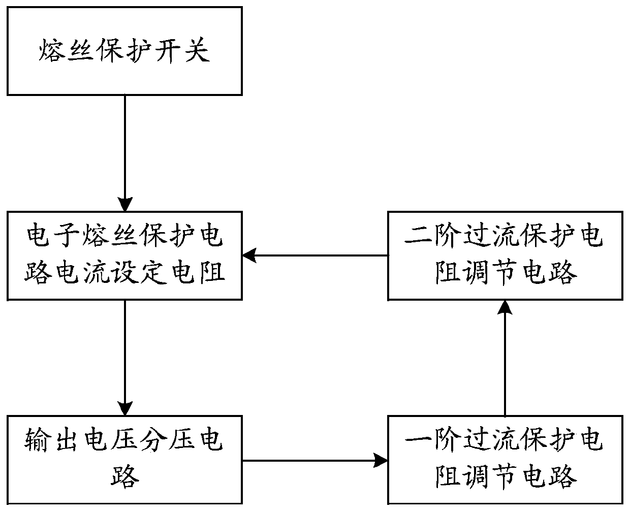
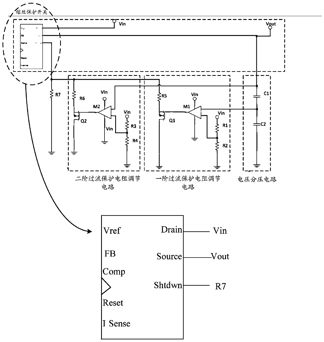
By connecting resistors of different resistances in parallel to the current setting resistors of the electronic fuse protection circuit, shunt protection is performed on the current setting resistors of the electronic fuse protection circuit according to the voltage conditions, which solves the problem of safety elimination caused by the fixed fuse current value

Method used


Image

  • Circuit overcurrent protection device and method
  • Circuit overcurrent protection device and method
  • Circuit overcurrent protection device and method

Examples


Embodiment Construction

[0033] In order to make the purpose, technical solution and advantages of the present invention more clear, the embodiments of the present invention will be described in detail below in conjunction with the accompanying drawings. It should be noted that, in the case of no conflict, the embodiments in the present application and the features in the embodiments can be combined arbitrarily with each other.

[0034] The steps shown in the flowcharts of the figures may be performed in a computer system, such as a set of computer-executable instructions. Also, although a logical order is shown in the flowcharts, in some cases the steps shown or described may be performed in an order different from that shown or described herein.

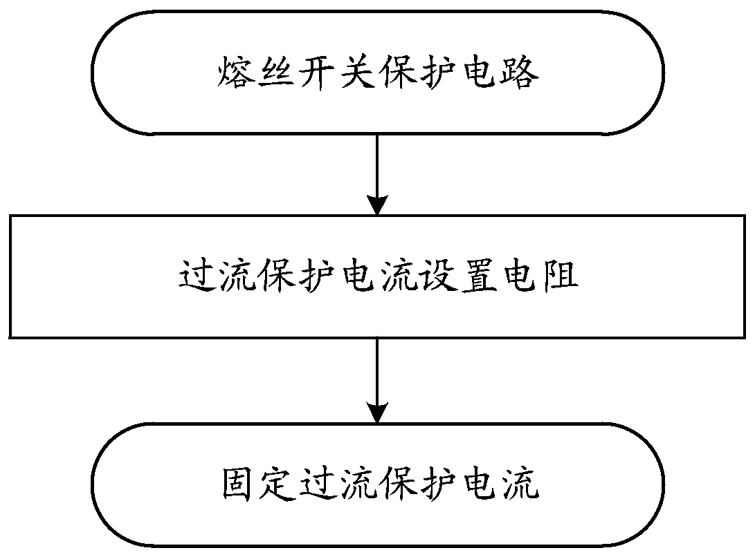
[0035] The existing technology is to fix the overcurrent protection current to correspond to all output environments, such as figure 1 As shown, it is impossible to adopt corresponding protection settings according to different situations, which brings hu...


PUM


Abstract

The invention discloses a circuit overcurrent protection device and method, relates to circuit fuse protection technology, and solves the problem that a fixed fusing current value causes a potential safety hazard. The device comprises an electronic fuse protection circuit current setting resistor, a voltage dividing circuit, a first-order overcurrent protection resistor adjusting circuit and a second-order overcurrent protection resistor adjusting circuit. The technical solution provided by the invention is suitable for circuit protection of electronic devices, and realizes a fuse protection scheme adapted to a voltage variation scenario.

Description

technical field [0001] The invention relates to circuit fusing protection technology, in particular to a circuit overcurrent protection device and method. Background technique [0002] The existing electronic fuse protection circuit relies on the external resistance of the corresponding pin to set the overcurrent protection current when the circuit is working. Once the corresponding resistance is selected, the protection current value is fixed. However, when the circuit starts to work, the output The voltage is low but the surge current caused by charging the capacitor at the output terminal is relatively large. In order to prevent false triggering, only a relatively large overcurrent protection value can be set. However, after normal operation, the output voltage reaches the preset value, but the current value is far away. If it is less than the set value of the overcurrent protection, the overcurrent protection point will be too high. When an abnormality occurs, it will no...

Claims


Application Information

Patent Timeline
IPC IPC(8): H02H3/08
Inventor 曹伟华
Owner ZHENGZHOU YUNHAI INFORMATION TECH CO LTD
Learn More