A kind of phase change graphene thermal pad, preparation method and application thereof

A heat-conducting gasket, graphene technology, applied in chemical instruments and methods, materials for heat exchange, cooling/ventilation/heating transformation, etc. Problems such as poor thermal conductivity of high-power devices, to achieve the effects of close contact, low thermal resistance, and low production costs

Active Publication Date: 2020-08-11
XIAMEN UNIV
View PDF7 Cites 0 Cited by
  • Summary
  • Abstract
  • Description
  • Claims
  • Application Information

AI Technical Summary

Problems solved by technology

[0002] Excessive chip temperature caused by poor heat dissipation is one of the main reasons for the failure of electronic devices. At present, high-power devices are bonded to heat sinks with thermally conductive adhesives, but the thermal conductivity of common thermally conductive adhesives is often less than 10W / mK, far Lower than the thermal conductivity of the device or heat sink, becoming a bottleneck in the thermal path
[0003] One of the schemes to replace the thermal conductive adhesive is to use a flexible thermal conductive gasket, place the flexible thermal conductive gasket between the high-power device and the heat sink, and lock it with fasteners, but the flexible thermal conductive gasket and the heat sink, the flexible heat sink and the The solid-solid interface between devices is often difficult to bond tightly for a long time, and there are often air gaps. Since air is a poor conductor of heat, it will cause poor thermal conductivity when high-power devices work.
Studies have shown that a closed-cavity heat sink wrapped with phase-change materials, the phase-change materials in the cavity gasify when the temperature rises, resulting in an increase in internal pressure, which strengthens the connection between the heat sink and the heat source, but the heat sink uses metal Substrate, the cost is high, and the sealing technology requirements for the heat sink are high, and the solid-solid contact with the heat sink and power devices is still

Method used


Image

  • A kind of phase change graphene thermal pad, preparation method and application thereof
  • A kind of phase change graphene thermal pad, preparation method and application thereof
  • A kind of phase change graphene thermal pad, preparation method and application thereof

Examples


Embodiment Construction

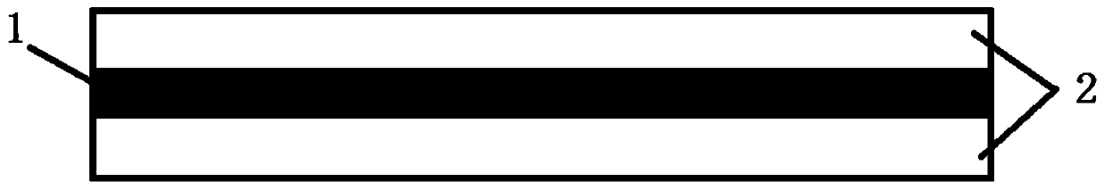
[0026] Please check Figure 1-4 , a preparation method of a phase-change graphene thermal pad of the present embodiment, comprising the steps of:

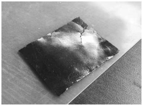
[0027] (1) Expanded graphite at 900°C, packed in a ziplock bag, repeatedly rolled into sheets by a double-roller rolling machine, soaked in GO solution for 2 days, dried in vacuum at 70°C for 24 hours, rolled tightly, and dried at 400°C Annealed in a water vapor atmosphere for 2 hours; the obtained intermediate layer 1 graphite sheet is as figure 2 shown;

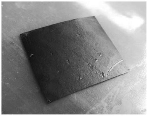
[0028] (2) The mass fraction of expanded graphite at 900°C is 75%, high-density polyethylene 15%, toughening agent POE-g-MAH 5%, and graphene oxide 5% are mixed and hot-pressed into sheets at 200°C to obtain the upper and lower layers of graphite / polymer phase change material sheet (coating layer 2) such as figure 2 shown.

[0029] (3) Take one piece of intermediate layer 1 obtained in step (1), stack the two pieces of cladding layer 2 obtained in step (2), center the gr...


PUM


Abstract

The invention discloses a phase-transition flexible graphene heat conduction pad, and a preparation method and application thereof. Expandable graphite is heated and expanded and then compacted into slices, immersed in an oxidized graphene solution for 1-3 days, dried in the vauum for 4-24 hours, and compacted and annealed at high temperature to serve as an intermediate layer; and a raw material including expandable graphite, oxidized graphene, a high-molecular phase-transition material and other additives is mixed and compacted into slices to serve as upper and low layers, and the upper and lower layers and the intermediate layer are overlapped and then heated and compacted into the pad. The obtained phase-transition flexible graphene heat conduction pad can be used among a large-power LED circuit board, a large-power device and a radiator.

Description

technical field [0001] The invention relates to a phase-change graphene thermal pad, a preparation method and an application thereof. Background technique [0002] Excessive chip temperature caused by poor heat dissipation is one of the main reasons for the failure of electronic devices. At present, high-power devices are bonded to heat sinks with thermally conductive adhesives, but the thermal conductivity of common thermally conductive adhesives is often less than 10W / mK, far Lower than the thermal conductivity of the device or heat sink, becoming a bottleneck on the thermal path. [0003] One of the schemes to replace the thermal conductive adhesive is to use a flexible thermal pad, place the flexible thermal pad between the high-power device and the heat sink, and lock it with fasteners, but the flexible thermal pad and the heat sink, the flexible heat sink and the The solid-solid interface between devices is often difficult to bond tightly for a long time, and there ar...

Claims


Application Information

Patent Timeline
Patent Type & Authority Patents(China)
IPC IPC(8): H05K7/20C09K5/06
Inventor 吕苗陈辛夷
Owner XIAMEN UNIV
Why Eureka
Try Eureka