

Workpiece lifting spraying production line
A production line and workpiece technology, applied in the field of workpiece hoisting and spraying production line, can solve the problems of inability to clean the surface of steel parts, affecting the painting of steel parts, and high labor intensity, and achieve the effect of avoiding spillage to the outside world, ensuring cleanliness, and low labor intensity
- Summary
- Abstract
- Description
- Claims
- Application Information
AI Technical Summary
Problems solved by technology
Method used
Image

Examples
Embodiment Construction
[0032] The present invention will be described in further detail below in conjunction with the accompanying drawings.
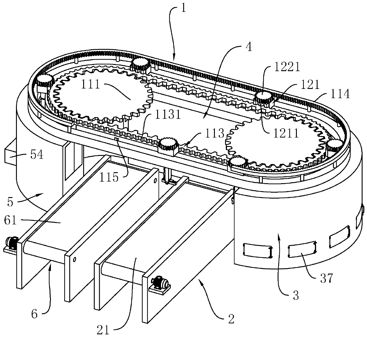
[0033] refer to figure 1 , is a workpiece hoisting and spraying production line disclosed in the present invention, comprising a hoisting conveying device 1, a loading station 2 on the lower side of the hoisting conveying device 1, a spraying station 33, a spraying station 4, and a drying station 5 and blanking station 6.
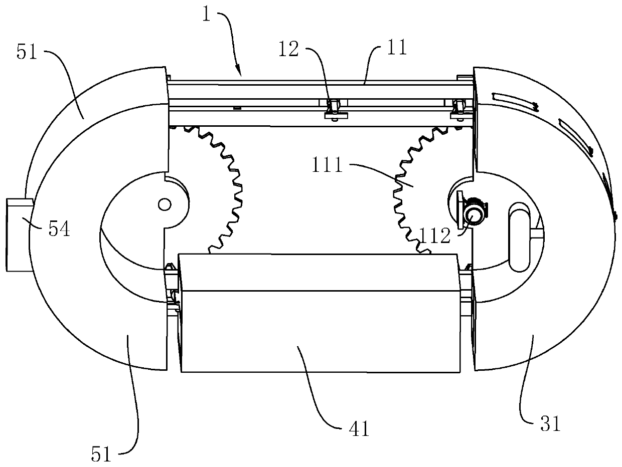
[0034] refer to figure 1 and figure 2 The hoisting conveying device 1 includes a conveying track 11 and a number of hoisting frames 12 arranged on the conveying track 11. The conveying track 11 has a waist-shaped ring structure, and both ends of the conveying track 11 are rotatably connected with a synchronous gear plate whose axis is vertically arranged. 111, the lower side of the transmission track 11 corresponding to a synchronous gear disc 111 is fixedly connected with a driving motor 112 capable of driving the synchronous gear disc ...
PUM
 Abstract
Description
Claims
Application Information