
Automatic feeding and discharging machine for deep hole drill of bar material

A technology of automatic loading and unloading and deep hole drilling, which is applied in boring/drilling, drilling/drilling equipment, metal processing, etc., and can solve problems such as high labor costs, easy hand pinching, and high labor intensity of workers

Pending Publication Date: 2019-05-10
李文福
View PDF0 Cites 7 Cited by
  • Summary
  • Abstract
  • Description
  • Claims
  • Application Information

AI Technical Summary

Problems solved by technology

[0003] The technical problem to be solved by the present invention is to provide an automatic loading and unloading machine for bar material deep hole drilling, which not only realizes that when one of the grabbing devices is feeding, the other grabbing device can simultaneously unload the material, and it also realizes the It can complete a series of operations such as automatic loading, automatic transmission, automatic retrieving, automatic processing, and automatic unloading and recycling of workpieces. The entire operation process does not require manual participation in loading and unloading, which reduces the labor intensity of workers and reduces The labor cost of the enterprise can be greatly improved, and the processing efficiency of the workpiece can be greatly improved, and the use is more convenient, safer and faster. It solves the problem that the current shaft deep hole drilling equipment on the market is manually loaded and unloaded. This operation The method not only has the disadvantages of low work efficiency, high labor intensity of workers and high labor cost of enterprises, but also the problem of pinching hands of workers in the process of loading materials.

Method used


Image

  • Automatic feeding and discharging machine for deep hole drill of bar material
  • Automatic feeding and discharging machine for deep hole drill of bar material
  • Automatic feeding and discharging machine for deep hole drill of bar material

Examples


Embodiment Construction

[0025] In order to facilitate the understanding of the present invention, the present invention will be described more fully below with reference to the associated drawings. Preferred embodiments of the invention are shown in the accompanying drawings. However, the present invention can be embodied in many different forms and is not limited to the embodiments described herein. On the contrary, the purpose of providing these embodiments is to make the disclosure of the present invention more thorough and comprehensive.

[0026] Unless otherwise defined, all technical and scientific terms used herein have the same meaning as commonly understood by one of ordinary skill in the technical field of the invention.

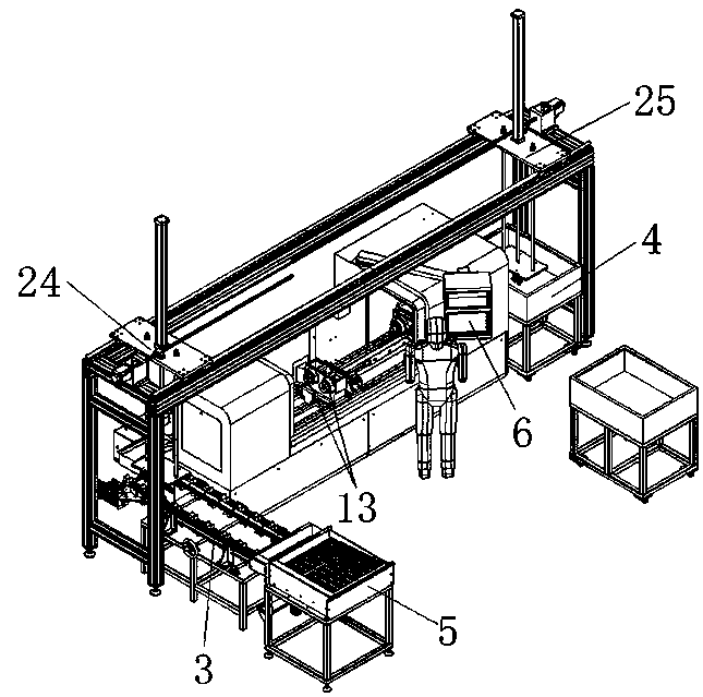
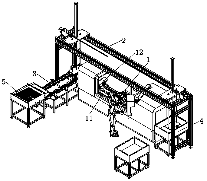
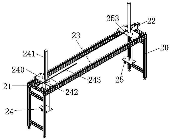
[0027] In this example, refer to Figure 1 to Figure 8 As shown, the bar material deep hole drilling automatic loading and unloading machine of the present invention includes a bar material drilling machine 1, a feeding mechanism 2 is arranged above the bar material dri...


PUM


Abstract

The invention provides an automatic feeding and discharging machine for deep hole drill of a bar material. The automatic feeding and discharging machine comprises a bar material drilling machine, a feeding mechanism, a conveying mechanism, a discharging bin device and a feeding bin device. According to the not only can the other grabbing device synchronously carry out discharging when one of grabbing devices is used for loading, but also the automatic feeding, automatic conveying, automatic material taking, automatic processing, automatic discharging and recycling and the like of a workpiece can be realized, and the whole operation process does not need to participate in feeding and discharging during the whole operation process, so that the labor intensity of workers is reduced, the laborcost of enterprises is reduced, the machining efficiency of the workpiece can be greatly improved, the use is more convenient, safer and more rapid, and the problems that because axial deep hole drilling in the market at present is fed and discharged by hands, the working efficiency is low, the labor intensity of workers is large, and the labor cost of the enterprises is high, and the hands cannot be clamped easily in the feeding process of the workers by the operation mode are solved.

Description

technical field [0001] The invention relates to an automatic loading and unloading machine for bar material deep hole drilling. Background technique [0002] In the production of large quantities of mechanical parts, the demand for the use of shaft parts is not only large, but also the machining accuracy of the inner holes of the shaft parts is very high, and the inner holes are generally processed by shaft deep hole drilling equipment In order to meet the requirements of use, but the shaft type deep hole drilling equipment currently on the market requires workers to put the bars to be processed on the machine tool one by one during the processing process. When the bars are processed, It also requires workers to remove the bars one by one from the machine tool for unloading. This kind of operation not only leads to the disadvantages of low processing efficiency, high labor intensity of workers and high labor cost of the enterprise, but also the workers are in the process of ...

Claims


Application Information

Patent Timeline
IPC IPC(8): B23Q7/03B23Q7/04B23Q7/10B23B41/02
Inventor 李文福闫宗卫江冠珊吴晓勇
Owner 李文福
Learn More