Pressure refueling pipeline outlet flow control device

A flow control and refueling pipeline technology, applied in the direction of liquid conveying devices, can solve the problems of turbulent flow and separated flow, causing danger, electrostatic discharge, etc., to increase the cross-sectional area of ​​the outlet flow, ensure the safety of refueling, and avoid excessive disturbance Effect

Active Publication Date: 2019-05-10
中航通飞华南飞机工业有限公司
View PDF7 Cites 0 Cited by
  • Summary
  • Abstract
  • Description
  • Claims
  • Application Information

AI Technical Summary

Problems solved by technology

[0003] Generally, when the aircraft is refueling under pressure, the outlet of the pipeline entering the fuel tank mostly adopts the structure of flute tube or bell mouth. The flow rate is not uniform, and it is easy to generate turbulent flow and separation flow, etc., which will cause excessive disturbance to the moisture and impurities deposited at the bottom of the fuel tank, and may cause electrostatic discharge, ignite the combustible fuel gas mixture, and cause danger

Method used


Image

  • Pressure refueling pipeline outlet flow control device
  • Pressure refueling pipeline outlet flow control device

Examples


Embodiment Construction

[0015] The specific implementation of the outlet flow control device of the pressure refueling pipeline of the present invention will now be described with reference to the accompanying drawings.

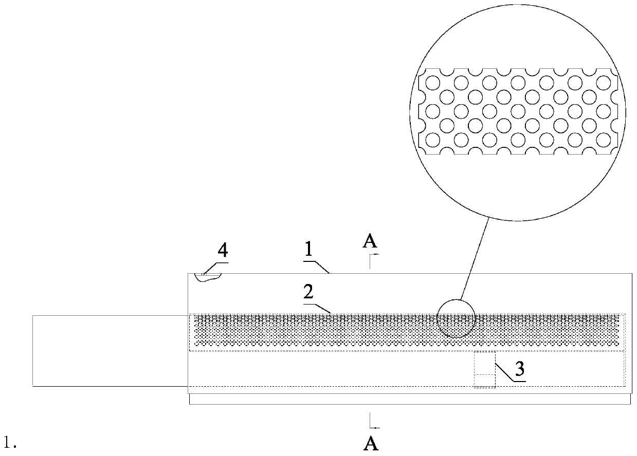
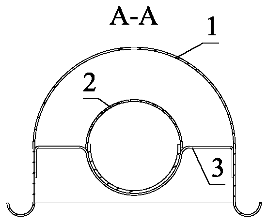
[0016] Such as figure 1 and figure 2 As shown, a pressure fueling pipeline outlet flow control device adopts the structure of porous outlet + baffle guide, which can make the fuel flow evenly and smoothly when the high-speed fuel enters the fuel tank. It is characterized in that when the refueling flow rate of the outlet flow control device of a single pressure refueling pipeline is about 25000L / h, the diameter of the porous pipe 2 is not less than 50mm, the length of the porous part is about 300mm, the diameter of a single through hole is 2mm, and the total small hole flow area is about 0.01m2, to ensure that the average outflow velocity of the fuel oil from the small hole is less than 1m / s, and the determination of the area takes into account the margin.

[0017] Take the metal...


PUM


Abstract

The invention discloses a pressure refueling pipeline outlet flow control device, which is characterized in that a perforated pipe (2) is connected to the tail end of a refueling pipeline, and a plurality of through holes are formed in the pipe wall of the perforated pipe (2); the front part of an outer cover (1) is welded to the perforated pipe (2) and reinforced by a supporting device (3), and an exhaust hole (4) is formed in the top of the outer cover (1); high-speed fuel enters the pressure refueling pipeline outlet flow control device, is then sprayed out of the through holes in the perforated pipe to the outer cover (1) and flows into the bottom of a fuel tank along the flow guide flanging of the outer cover (1). According to the pressure refueling pipeline outlet flow control device, high-speed fuel oil is decelerated after entering the fuel tank during pressure refueling, meanwhile, it is guaranteed that the decelerated fuel oil flows uniformly and slowly, excessive disturbanceand possible electrostatic discharge to deposited water and impurities at the bottom of the fuel tank are avoided, and refueling safety is guaranteed.

Description

technical field [0001] The invention belongs to the field of aircraft pressure refueling system equipment, and relates to a pressure refueling pipeline outlet flow control device. Background technique [0002] When the aircraft is refueled under pressure, the flow rate is usually large to meet the requirements of short refueling time. When the hydrocarbon liquid flows through metal surfaces, such as refueling pipes, filters, nozzles, fuel tanks and airframe pipelines, electrostatic charges will be generated. Therefore, the airworthiness advisory circular proposes that the flow velocity at the outlet of the fuel tank should not be greater than 1m / s during pressure refueling, and not greater than 7m / s after being submerged. At the same time, it is also proposed to ensure that the fuel entering the fuel tank does not excessively disturb the water and impurities deposited at the bottom of the fuel tank, and the outlet should be located at a lower position in the fuel tank. The r...

Claims


Application Information

Patent Timeline
Patent Type & Authority Applications(China)
IPC IPC(8): B64F1/28
CPCY02T50/40
Inventor 滕叶王乐游波陈明生田傲
Owner 中航通飞华南飞机工业有限公司
Why Eureka
Try Eureka