Large-area and high-thermal-conductivity light and thin microgroove flat heat tube

A flat plate heat pipe, high thermal conductivity technology, used in indirect heat exchangers, lighting and heating equipment, etc., can solve the limitations of flat heat pipe flatness and maximum width, wire mesh heat pipes limit maximum heat flux, void space and number of through holes Limitation and other issues to achieve the effect of improving repeatability, meeting the heat dissipation requirements of large heat flux density and high power, and avoiding the risk of fracture

Inactive Publication Date: 2016-03-16
BEIJING SATELLITE MFG FACTORY
View PDF5 Cites 3 Cited by
  • Summary
  • Abstract
  • Description
  • Claims
  • Application Information

AI Technical Summary

Problems solved by technology

[0004] The current flat heat pipe is filled with capillary wire mesh, and its internal wire mesh is made of sintered metal particles. The porosity and the number of through holes are limited by the existing technology and structure. Under the condition of using the same filling fluid, Wire mesh heat pipes limit their maximum heat flux
In addition, the processing method of the existing flat heat pipe adopts extrusion molding, which limits the flatness and maximum width of the flat heat pipe, and there is no reinforcing rib inside, making it unable to support the load, and cannot be used in some occasions that require load bearing

Method used


Image

  • Large-area and high-thermal-conductivity light and thin microgroove flat heat tube
  • Large-area and high-thermal-conductivity light and thin microgroove flat heat tube
  • Large-area and high-thermal-conductivity light and thin microgroove flat heat tube

Examples


Embodiment Construction

[0026] Below in conjunction with accompanying drawing and specific embodiment the present invention is described in further detail:

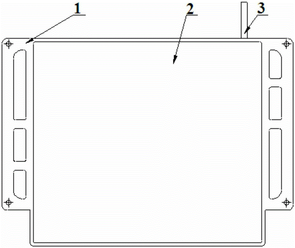
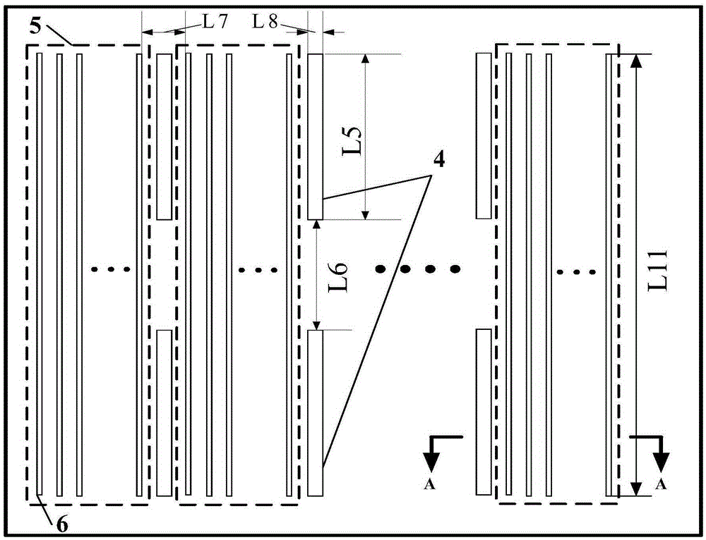
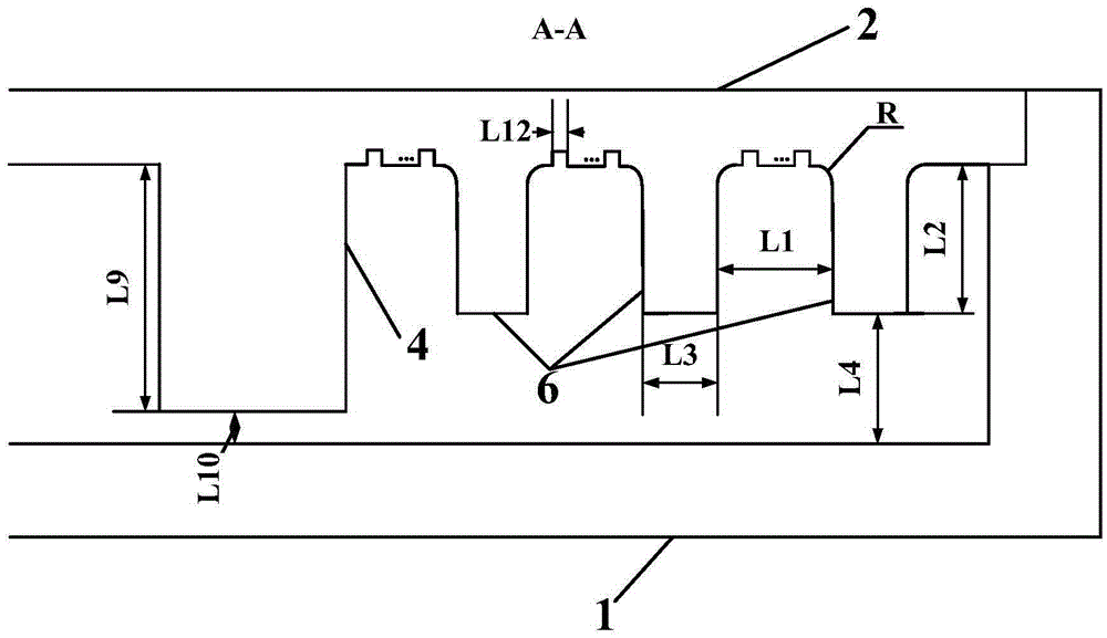
[0027] Such as figure 1 Shown is a schematic diagram of the structure of a large-area light and thin high-thermal conductivity micro-groove plate heat pipe. It can be seen from the figure that it includes a micro-groove shell 1, a micro-groove cover 2 and a liquid filling tube 3; the micro-groove cover 2 is fixedly installed in the micro-groove The upper surface of the housing 1 and the lower surface of the microgroove cover 2 are provided with reinforcing ribs 4; the liquid filling tube 3 is fixedly installed on one side of the microgroove housing 1.

[0028] The three form a closed space and fill a certain amount of liquid working medium inside. Through the air cavity formed by the micro-groove cover plate 1 and the micro-operating shell 2, the internal working medium is evaporated and condensed by heating and cooling. The array provides the ...


PUM


Abstract

The invention discloses a large-area and high-thermal-conductivity light and thin microgroove flat heat tube, and belongs to the field of microgroove flat thermal control engineering. The large-area and high-thermal-conductivity light and thin microgroove flat heat tube comprises a microgroove shell, a microgroove cover plate and a liquid filling pipe, wherein the microgroove cover plate is fixedly mounted at the upper part of the microgroove shell; a reinforcing rib is arranged at the lower part of the microgroove cover plate; and the liquid filling pipe is fixedly mounted at the right side of the upper end of the microgroove shell. The invention provides the large-area and high-thermal-conductivity light and thin microgroove flat heat tube; firstly, a capillary structure, the cover plate and the shell are connected to form a complete sealing structure through modes of electronic beam welding, TIG welding and dissimilar metal brazing, so that the high heating flux can be realized, and the heat transfer on the larger heat transfer contact area is efficient and reliable; and the large-area and high-thermal-conductivity light and thin microgroove flat heat tube is relatively lighter in whole weight and higher in structural strength, can serve as a structural part and a bearing part, and is convenient for use. The large-area and high-thermal-conductivity light and thin microgroove flat heat tube reduces the system complexity, and improves the system reliability.

Description

technical field [0001] The invention relates to the field of thermal control engineering of a micro-channel flat plate, in particular to a large-area light and thin high-thermal-conduction micro-channel flat heat pipe. Background technique [0002] Heat pipes are an important part of thermal control systems and environmental control systems. Heat pipes are needed between the heat sources, cold sources, and heat sinks of each system to transfer heat, reduce system complexity, and improve system reliability. [0003] Heat pipes are currently widely used in thermal control systems such as aerospace, weaponry, and ground products. They are widely used in military and civilian fields. Compared with conventional heat pipes, flat heat pipes have a large thermal contact area, small thickness, and light weight. And other characteristics, it has its unique advantages in solving the heat transfer problem of concentrated point heat source and large area heat source. [0004] The curren...

Claims


Application Information

Patent Timeline
Patent Type & Authority Applications(China)
IPC IPC(8): F28D15/02
Inventor 谢文刘建峰张玉良葛一凡李星付振东刘淑芳
Owner BEIJING SATELLITE MFG FACTORY
Why Eureka
Try Eureka