Compressed gas refrigerated dryer heat exchanging water removal structure

A technology of compressing gas and drying machine, applied in the direction of heat exchanger shell, indirect heat exchanger, heat exchanger type, etc., it can solve the problem that liquid is easily taken away by air flow, condensate is easy to freeze, and plate gap is small problems, to achieve the effects of reducing the risk of corrosion leakage and solder joint leakage, good gas-liquid separation effect, and high material utilization rate

Pending Publication Date: 2019-10-25
FOSHAN TIANDI YUANYI PURIFICATION EQUIP
View PDF0 Cites 4 Cited by
  • Summary
  • Abstract
  • Description
  • Claims
  • Application Information

AI Technical Summary

Problems solved by technology

[0002] The heat exchange structures of existing compressed air dryers mainly include the following categories: The first category is the heat exchange structure of general refrigerated dryers, such as Image 6 As shown, 1a-cooling and heat exchanger, 2a-evaporator, 3a-gas-liquid separator are made of separate barrels, the structure is complicated, the production is complicated, and the volume is huge. The evaporator adopts copper-aluminum fin type or stainless steel fin type. Heater, the fin gap is small, the condensate is easy to freeze in the evaporator, resulting in ice blockage
The second type, plate or plate-fin type cold dryer heat exchanger, such as Figure 7 As shown, this heat exchange structure has the following problems: 1. Aluminum plate-fin heat exchangers or stainless steel plate heat exchangers are used for cold and heat exchange and evaporators, and the welding joints are easy to leak and cannot be repaired; 2. The plates are thin , is also easy to corrode and perforate and cannot be repaired; 3. Due to the small size, the gas-liquid separation effect is not good; if an external gas-liquid separator is installed, the compact structure cannot be achieved; 4. The gap between the plates is small, and it is easy to be dirty. Blockage, the accumulation of more dirt will affect the heat transfer effect, and the resistance will increase, making the pressure difference between the inlet and outlet of the compressed air more and more large, and the condensate is easy to freeze in the evaporator to block the compressed air channel, resulting in ice blockage Phenomenon; 5. The production is complicated, only professional plate or plate-fin heat exchanger manufacturers can make it, and the cost is high
The third category is a cold dryer with a cold heat exchanger and an evaporator built in a bucket, such as Figure 8 As shown in the figure: a-refrigerant inlet, b-refrigerant outlet, h-air inlet, i-air outlet, g-spiral tube, e-filter net, f-evaporator, the evaporator uses copper and aluminum fins Type or stainless steel fin heat exchanger, this structure has the following problems: 1) the fin gap is small, the condensate is easy to freeze in the evaporator, resulting in ice blockage; 2) there is no special gas-liquid separation device, and It relies on natural gravity to separate the liquid, the liquid is easily taken away by the air flow, and the gas-liquid separation effect is not good; 3) The production precision is high, the production process is complicated, and the cost is high
[0003] To sum up, the heat exchange structure of existing compressed air dryers is not ideal

Method used


Image

  • Compressed gas refrigerated dryer heat exchanging water removal structure
  • Compressed gas refrigerated dryer heat exchanging water removal structure
  • Compressed gas refrigerated dryer heat exchanging water removal structure

Examples


Embodiment 1

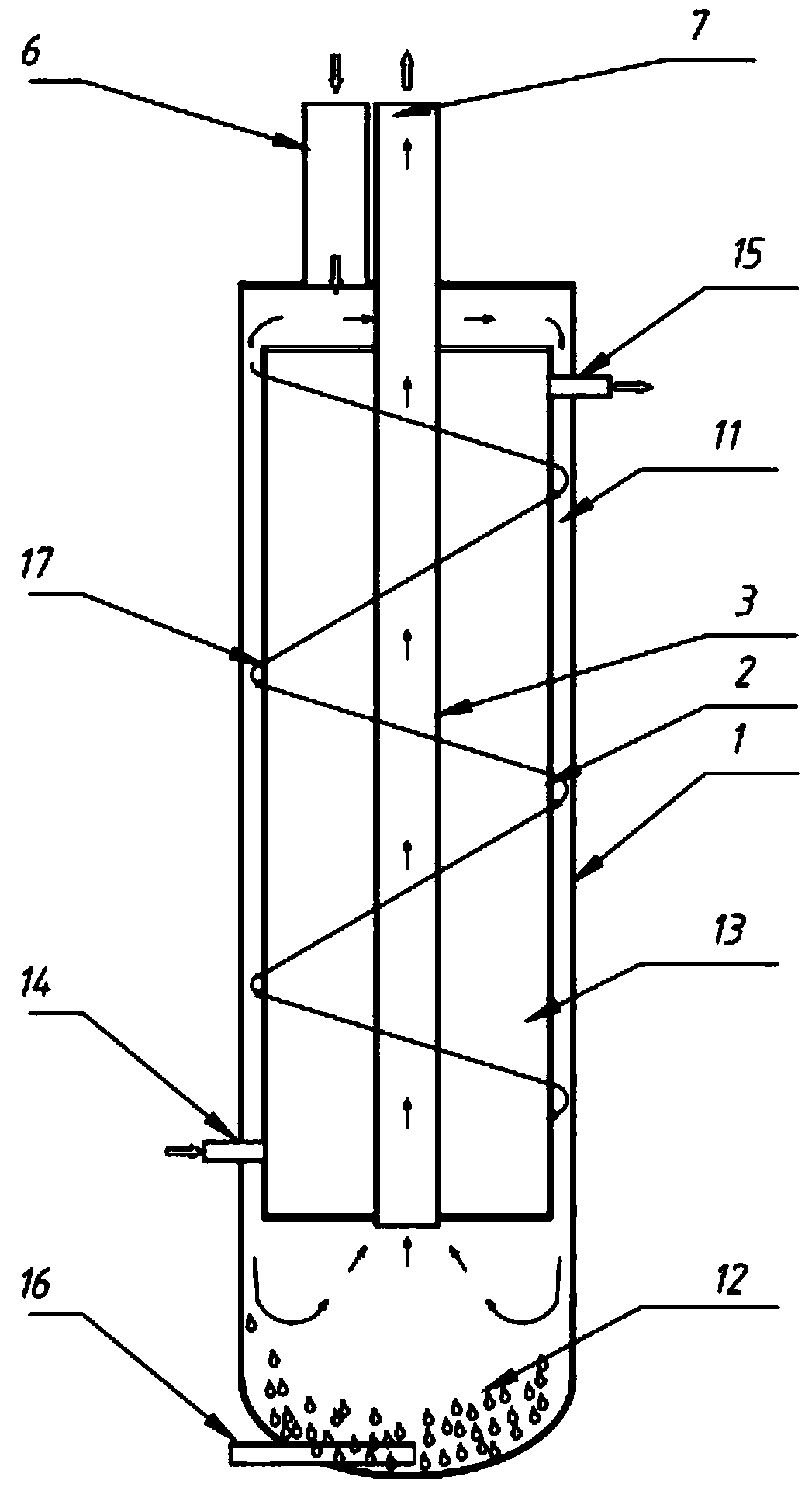
[0032] Embodiment 1: refer to figure 1 , the present invention provides a heat exchange and water removal structure for a compressed gas refrigeration dryer, which includes a vertically arranged first tube 1 and a second tube 2 inside the first tube 1. The outer diameter of the second tube 2 is Smaller than the inner diameter of the first tube 1, and the second tube 2 is preferably coaxially arranged with the first tube 1, the bottom of the second tube 2 does not touch the bottom of the first tube 1, the first tube 1 and the second tube 2 A gas-liquid separation chamber 11 is formed between them, and a spiral piece 17 is arranged in the gas-liquid separation chamber 11 . The liquid collecting chamber 12 is formed at the bottom of the gas-liquid separation chamber 11, the bottom of the second pipe 2 is closed, and the top is also closed, and a cooling chamber 13 is arranged inside, and the cooling chamber 13 is respectively provided with a cooling source outlet 15 and a The c...

Embodiment 2

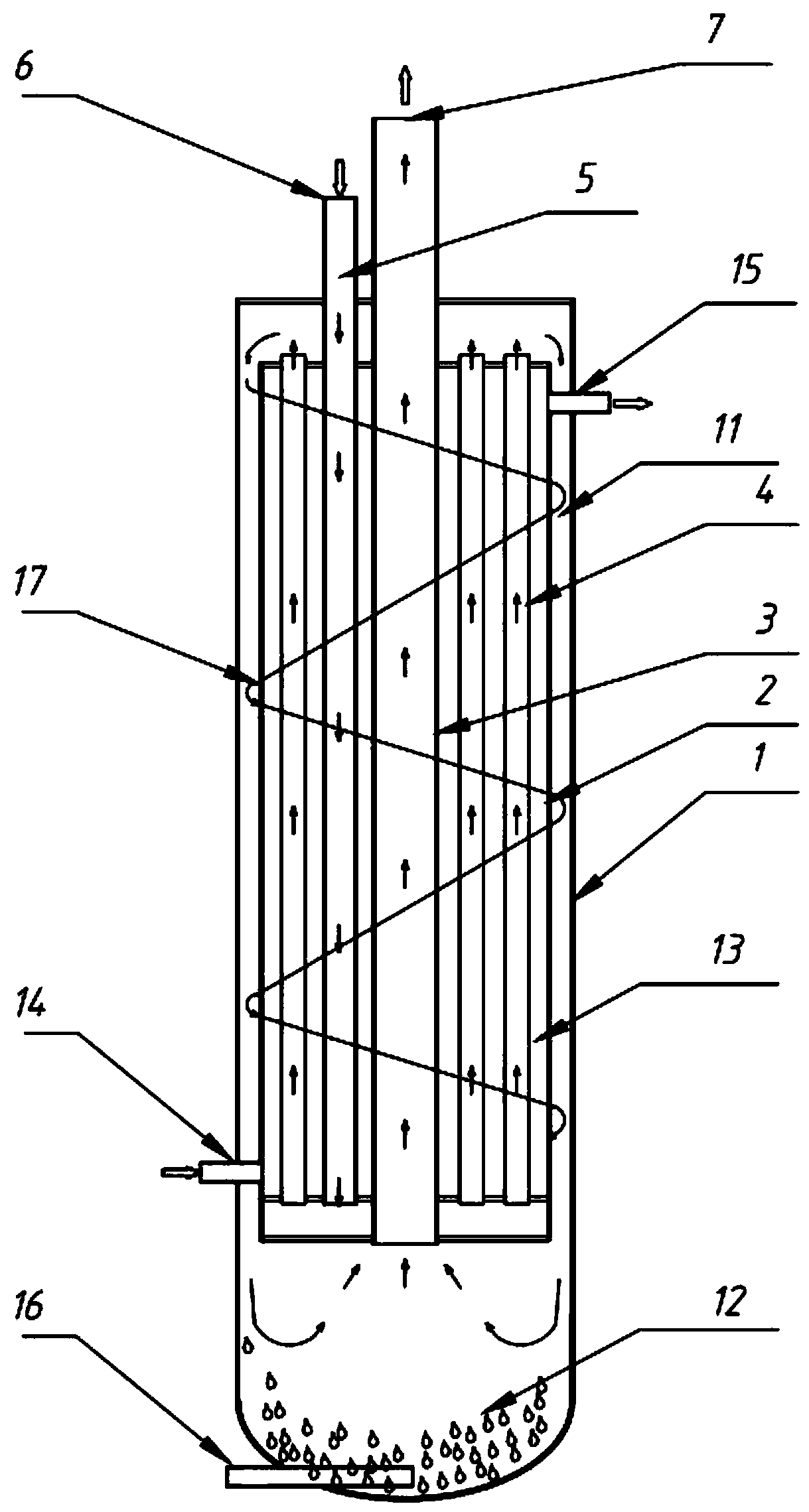
[0042] Embodiment 2: refer to figure 2Compared with Embodiment 1, the difference is that one or more fourth tubes 4 are provided in the refrigeration chamber 13 to increase the heat exchange area, and the upper part of the gas-liquid separation chamber 11 passes through the fourth pipe 4. The pipe 4 communicates with the gas inlet 6 , wherein the gas inlet 6 communicates with the bottom of the refrigeration chamber 13 through the fifth pipe 5 . In this way, the gas enters the bottom of the refrigeration chamber 13 through the fifth pipe 5, and then enters the fourth pipe 4. The gas performs a heat exchange with the cooling source on the inside of the fourth pipe 4 and the outside of the fourth pipe 4, and then reaches the upper part of the gas-liquid separation chamber 11. , flowing downward from the upper part of the gas-liquid separation chamber 11, under the action of the spiral piece 17, the compressed gas descends in a spiral manner, the compressed gas contacts the outer...

Embodiment 3

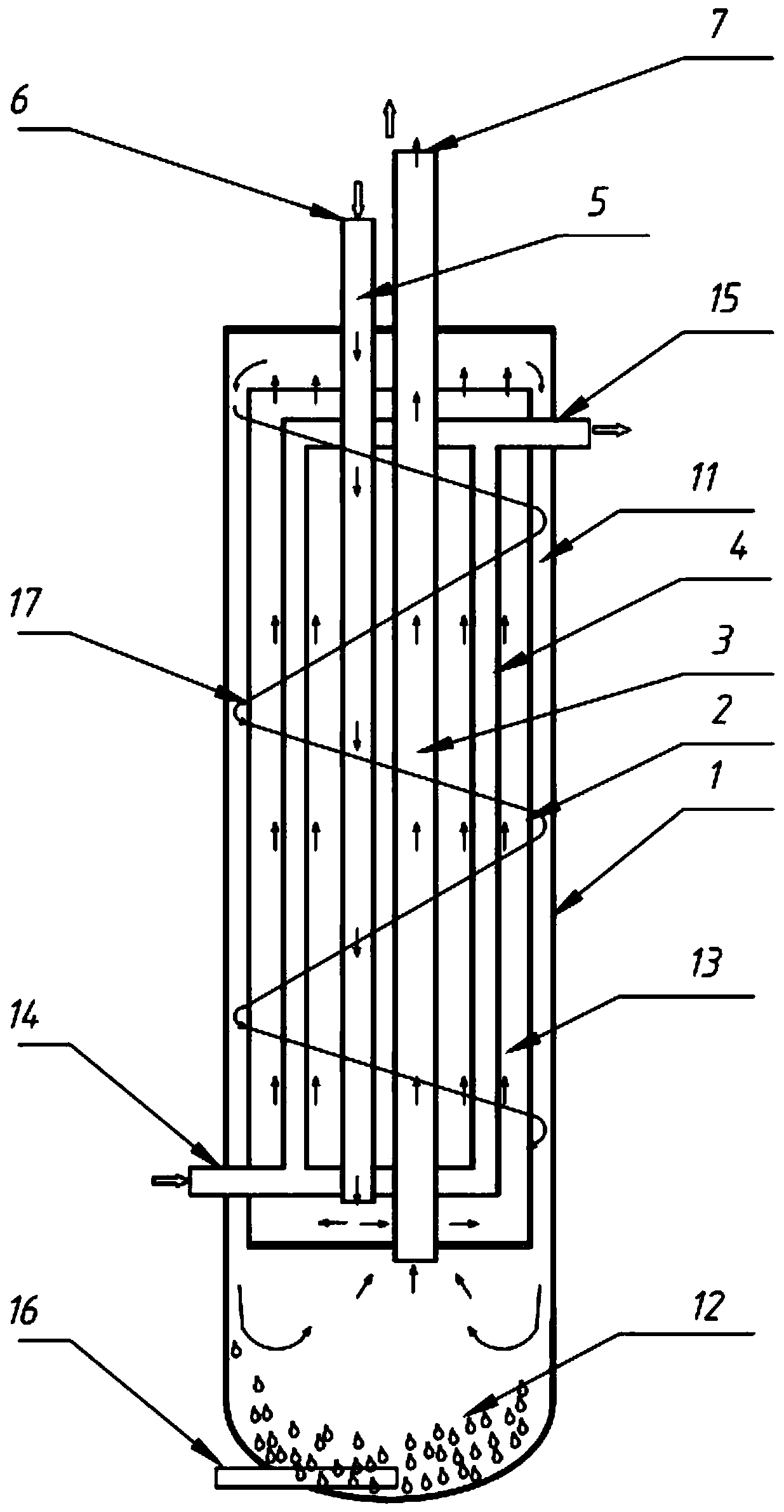
[0051] Embodiment 3: refer to image 3 Compared with Embodiment 2, the difference is that the upper part of the refrigeration chamber 13 is not closed, but the bottom is closed, the fourth pipe 4 is arranged in the refrigeration chamber 13, and the two ends of the fourth pipe 4 are respectively connected to the refrigeration source outlet 15 and the refrigeration source inlet 14 , the low-temperature refrigeration source flows in the fourth pipe 4 , and the compressed gas flows outside the fourth pipe 4 . In this way, the gas enters the bottom of the refrigeration chamber 13 through the fifth pipe 5, flows upwards in the refrigeration chamber 13, conducts a heat exchange with the low-temperature refrigeration source inside the fourth pipe 4, and then lowers the temperature, and then reaches the upper part of the gas-liquid separation chamber 11, from The upper part of the gas-liquid separation chamber 11 flows downward, and the compressed gas generates centrifugal force during...


PUM


Abstract

The invention provides a compressed gas refrigerated dryer heat exchanging water removal structure which can improve the problems that the existing equipment is not impact in structure, and poor in gas and water separating effect and can cause ice blockage easily, and the inlet and outlet differential pressure of compressed gas is large. The compressed gas refrigerated dryer heat exchanging waterremoval structure comprises a first pipe vertically arranged, and a second pipe arranged in the first pipe, wherein the bottom of the second pipe is not in contact with the bottom of the first pipe; agas-liquid separation cavity is formed between the first pipe and the second pipe; a liquid collecting cavity is formed in the bottom of the gas-liquid separation cavity; a refrigerating cavity is formed in the second pipe and is provided with a refrigerating source outlet and a refrigerating source inlet; the refrigerating cavity communicates with a gas inlet; the compressed gas refrigerated dryer heat exchanging water removal structure further comprises one or more third pipes; one end of the third pipe communicates with the external world and serves as a gas outlet; the other end of the third pipe communicates with the upper part of the liquid collecting cavity; the gas enters from the gas inlet, is cooled through the refrigerating cavity and is subjected to gas-water separation through the gas-liquid separation cavity, then, condensate separates out and flows to the liquid collecting cavity, and the gas is discharged out of the gas outlet through the third pipe.

Description

technical field [0001] The invention relates to the technical field of gas dryers, in particular to a heat exchange and water removal structure of a compressed gas refrigeration dryer. Background technique [0002] The heat exchange structures of existing compressed air dryers mainly include the following categories: The first category is the heat exchange structure of general refrigerated dryers, such as Image 6 As shown, 1a-cooling and heat exchanger, 2a-evaporator, 3a-gas-liquid separator are made of separate barrels, the structure is complicated, the production is complicated, and the volume is huge. The evaporator adopts copper-aluminum fin type or stainless steel fin type. Heater, the fin gap is small, the condensate is easy to freeze in the evaporator, resulting in ice blockage. The second type, plate or plate-fin type cold dryer heat exchanger, such as Figure 7 As shown, this heat exchange structure has the following problems: 1. Aluminum plate-fin heat exchangers...

Claims


Application Information

Patent Timeline
Patent Type & Authority Applications(China)
IPC IPC(8): F28D7/00F28F1/36F28F9/22F28F9/24B01D53/26
CPCB01D53/002B01D53/265F28D7/0066F28F1/36F28F9/22F28F9/24F28F2009/224
Inventor 廖志远
Owner FOSHAN TIANDI YUANYI PURIFICATION EQUIP
Why Eureka
Try Eureka