Spliced steel arch frame and manufacturing method thereof

A steel arch and splicing technology, which is applied in earthwork drilling, wellbore lining, tunnel lining, etc., can solve problems such as unsuitable support specifications, delays in construction period, and inappropriate arch radians, etc., so as to reduce the defective rate, Ease of transportation and simple structure

Inactive Publication Date: 2019-05-10
CCCC SHEC DONGMENG ENG CO LTD
View PDF7 Cites 4 Cited by
  • Summary
  • Abstract
  • Description
  • Claims
  • Application Information

AI Technical Summary

Problems solved by technology

The one-piece steel arch frame is more complicated to manufacture, and it is more difficult to store and transport. Special equipment is required for transport and erection when splicing.
However, the spliced ​​steel arch frame will have the problem that the adjacent arch brackets are not tightly spliced ​​due to insufficient arc and verticality of the arch brackets, which reduces the supporting effect.
[0004] Moreover, the tunnel support construction has a strong cyclic operation. In traditional construction, in order to save time, the trial assembly of steel arches is not carried out, and the support work of steel arches is directly carried out in the tunnel. For integrated steel arches, arches often appear If the radian is not suitable, the steel arch needs to be removed and re-erected
For the spliced ​​steel arch frame, there are often cases where the deformation arc is not enough, the connection of the steel arch bracket is not tight, the bracket specifications are different, and the height of the steel arch frame is not suitable after splicing. It is necessary to disassemble the steel arch frame and reinstall it. set up
Reduce the effect of construction support, delay the construction period, and increase support costs

Method used


Image

  • Spliced steel arch frame and manufacturing method thereof
  • Spliced steel arch frame and manufacturing method thereof
  • Spliced steel arch frame and manufacturing method thereof

Examples


Embodiment 1

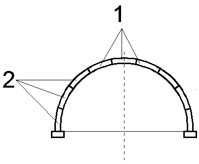
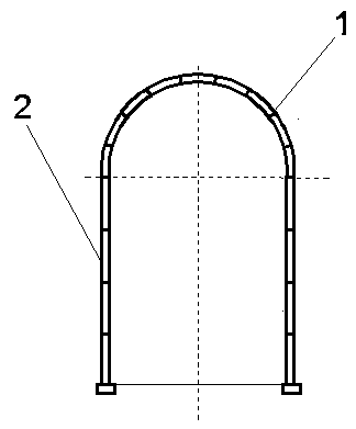
[0034] see figure 1 As shown, a spliced ​​semicircular steel arch frame, arch support 1 and two mirror-symmetrical side wall supports 2, the center line between the center of the arch support 1 and the center of the tunnel is perpendicular to the tunnel ground, and the arch support 1 It is fixedly connected with the side wall bracket 2 by bolts.

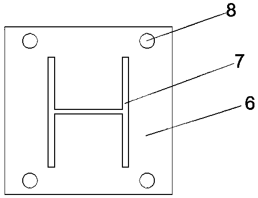
[0035] The first bracket and the second bracket have the same length and the same deformation arc, and are composed of section steel and connecting steel plate 6. The center of the connecting steel plate 6 coincides with the center of the end of the section steel. The section steel is preferably I-beam, and the connecting steel plate 6 is vertically welded Two sets of symmetrical connecting holes 8 are provided on the connecting steel plate 6 at the end of the I-beam, and each group of connecting holes 8 has two.

[0036] There are 9 first brackets and second brackets in total, including 1 first bracket as a vault bracket 1, and a s...

Embodiment 2

[0039] see figure 1 As shown, a spliced ​​semicircular steel arch frame, arch support 1 and two mirror-symmetrical side wall supports 2, the center line between the center of the arch support 1 and the center of the tunnel is perpendicular to the tunnel ground, and the arch support 1 It is fixedly connected with the side wall bracket 2 by bolts.

[0040]The first bracket and the second bracket have the same length and the same deformation arc, and are composed of section steel and connecting steel plate 6. The center of the connecting steel plate 6 coincides with the center of the end of the section steel. The connecting steel plate 6 is vertically welded on the end of the section steel, and the connecting steel plate 6 There are two groups of symmetrical connection holes 8 on the top, each group of connection holes 8 has two.

[0041] There are 12 first brackets and second brackets in total, including the arch bracket 1 composed of 2 first brackets connected by high-strength...

Embodiment 3

[0045] see figure 2 As shown, a spliced ​​circular arch straight wall steel arch frame, the arch bracket 1 is a semicircular arch frame, the two side wall brackets 2 are vertical arch frames, and the center of the arch bracket center 1 is connected to the center of the tunnel Vertical to the tunnel ground, the vault support 1 and the side wall support 2 are fixedly connected by bolts.

[0046] Vault bracket 1 is composed of 5 first brackets fixedly connected by bolts. The deformation arc of the first brackets is 36°. Side wall arch frame 2 is composed of 8 second brackets connected by bolts. The second brackets are not deformed. The lengths of the shaped steel of the first bracket and the second bracket are the same or different.

[0047] Both the first bracket and the second bracket are made up of shaped steel and connecting steel plate 6, the center of connecting steel plate 6 coincides with the center of the end of shaped steel 3, connecting steel plate 6 is vertically we...


PUM


Abstract

The invention provides a splicing steel arch frame. The splicing type steel arch frame comprises a vault support and two side wall supports located at the two ends of the vault support. The vault support is formed by connecting a plurality of first supports, and each side wall support is formed by connecting a plurality of second supports. The first supports and the second supports each comprise profile steel and a connecting steel plate; the connecting steel plates are perpendicularly welded to the ends of the two ends of the profile steel, and two sets of symmetrical connecting holes are formed in the connecting steel plates. Profile steel for manufacturing the first supports and the second supports is the same in length and width, a groove for positioning and inserting the profile steelis milled in the center of each connecting steel plate, and the shape and the size of the section of the groove are the same as those of the profile steel. The manufacturing method of the steel archframe comprises the steps of: steel arch frame design; material preparation; cold bending deformation and welding; and storage. The splicing steel arch frame has the advantages of being simple in structure, tight in connection and convenient to store and transport; and the manufacturing method of the splicing steel arch frame enables the steel arch frame to achieve process operation, and the rateof finished products is high.

Description

technical field [0001] The invention relates to the technical field of tunnel initial support, in particular to a spliced ​​steel arch frame and a manufacturing method thereof. Background technique [0002] With the continuous expansion of the scale and speed of my country's road traffic construction, tunnel engineering has become one of the very important construction links. During the tunnel construction process, it is necessary to use steel arches for initial support of the tunnel, so that To ensure the safety and stability of the construction, it is necessary to ensure the strength of the steel arch. [0003] The traditional steel arch has two structures, one is a semicircular steel arch, and the other is a circular arch straight wall steel arch. The round arch straight wall steel arch frame is generally composed of three steel brackets, that is, the top semicircular bracket and the vertical side wall brackets on both sides. The specifications of the top bracket and the...

Claims


Application Information

Patent Timeline
Patent Type & Authority Applications(China)
IPC IPC(8): E21D11/18E21D11/30B23P15/00
Inventor 马保亮
Owner CCCC SHEC DONGMENG ENG CO LTD
Why Eureka
Try Eureka