Impeller pipeline power generation device

A power generation device and impeller technology, which is applied to electromechanical devices, hydroelectric power generation, electrical components, etc., can solve the problem that the kinetic energy of fluid cannot be effectively utilized, and achieve the effect of solving the difficulty in starting the impeller, accelerating the water flow rate, and driving the impeller with strong ability.

Inactive Publication Date: 2019-05-10
TIANJIN UNIV
View PDF1 Cites 0 Cited by
  • Summary
  • Abstract
  • Description
  • Claims
  • Application Information

AI Technical Summary

Problems solved by technology

[0006] The purpose of the present invention is to overcome the deficiencies in the prior art, aim at the problem that the kinetic energy of the fluid in the pipeline cannot be effectively utilized, and provide an impeller pipeline power generation device. , to solve part of the daily electricity demand

Method used


Image

  • Impeller pipeline power generation device
  • Impeller pipeline power generation device
  • Impeller pipeline power generation device

Examples


Embodiment Construction

[0024] The present invention will be further described below in conjunction with the accompanying drawings.

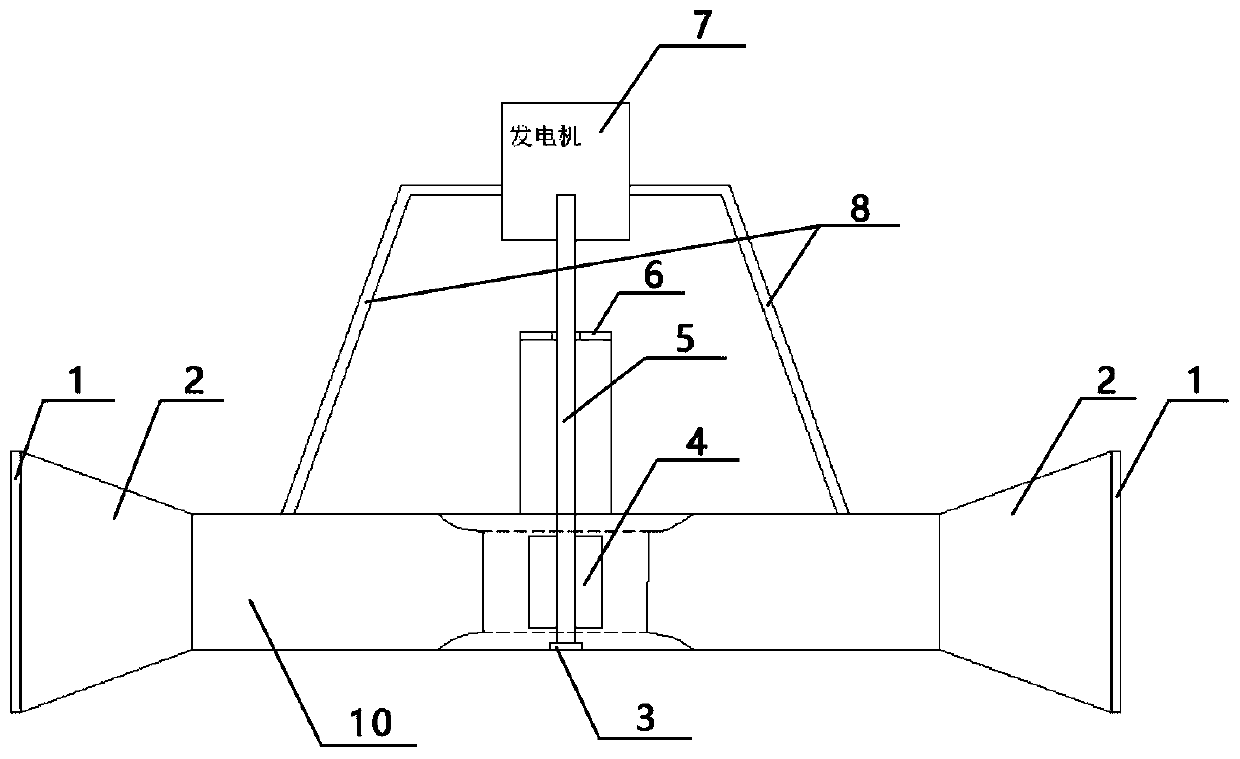
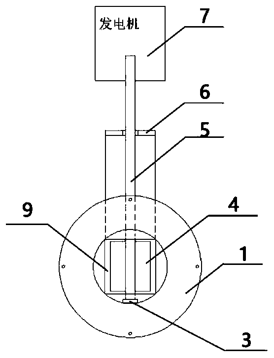
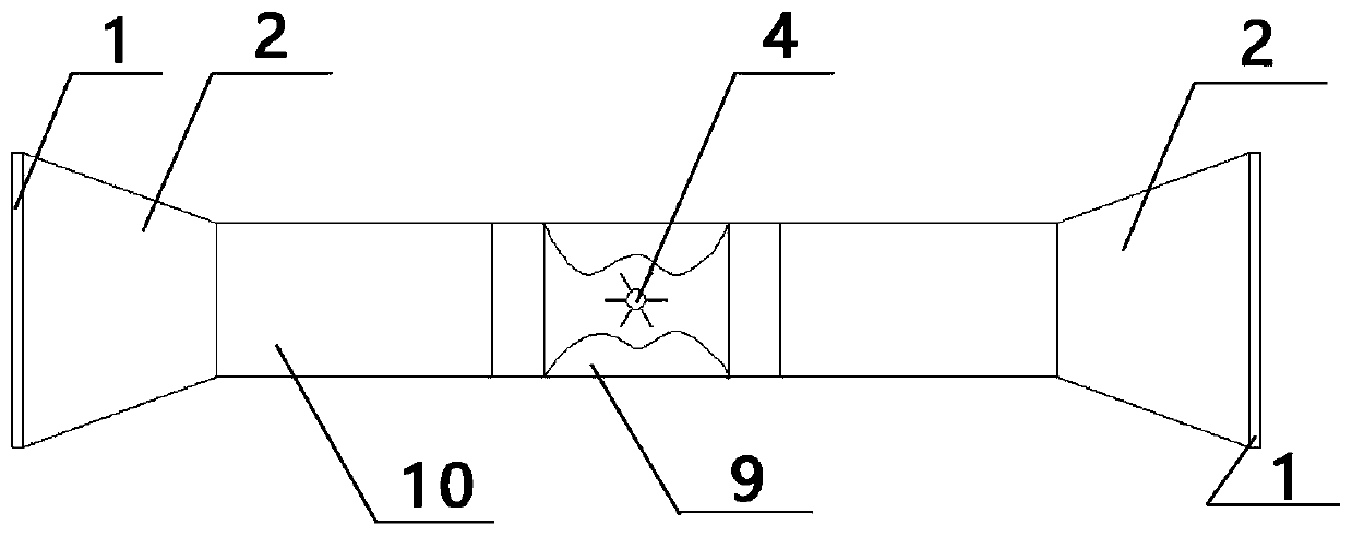
[0025] Such as Figure 1 to Figure 4 As shown, an impeller tube power generation device, the main body of the device is composed of a generator 7, a built-in impeller 4, a shroud 9 and a casing 10. Both ends of the casing 10 are connected to the pipeline through the flange 1, and a rubber ring is installed for waterproof sealing, wherein at the incoming flow end of the casing 10 is a tapered structure 2 with variable cross-section, and the cross-section of the tapered structure 2 is sequential from outside to inside Reduced, the top of the shell 10 is provided with a circular pipe; in order to match the size of the external pipe and facilitate connection, the outlet end is also set to the same tapered structure 2. Inside the casing 10, the shroud 9 is welded and fixed to the inner wall of the casing 10, and the shroud 9 is a hyperbolic symmetrical structure; a bearing...


PUM


Abstract

The invention discloses an impeller pipeline power generation device arranged on a pipeline. The power generation device is composed of a shell, an impeller unit and a power generator unit; the two ends of the shell are each of a conical structure with the section gradually decreased from outside to inside, and the structures are used for increasing the flowing speed of incoming flow; the two endsof the shell are provided with flanges connected with the pipeline and are subjected to waterproof sealing through rubber rings; a circular pipeline is arranged on the top of the shell; the impellerunit comprises a fairing, an impeller, a main shaft and a coupler; the fairing is located at the position, below the circular pipeline, of the interior of the shell and is welded to the inner wall ofthe shell; a bearing is arranged at the bottom of the inner side of the shell; the impeller is fixed to the bearing; a rotary shaft of the impeller is connected with the main shaft through the coupler; the power generator unit comprises a power generator, a support and a waterproof sealing bearing; the waterproof sealing bearing is arranged above the circular pipeline; the main shaft penetrates through an inner hole; the top end of the main shaft is connected with a rotor of a power generator; and a stator of the power generator is connected with the shell through the support. The device can routinize power generation, and solve part of daily power demands.

Description

technical field [0001] The invention relates to the field of hydroelectric power generation, in particular to an impeller pipeline power generation device placed in a low water level difference zone. Background technique [0002] At present, hydropower is already a very important way of generating electricity. Hydropower generation is to use rivers, lakes, etc. to flow water with potential energy from high places to low places, convert the potential energy contained in it into kinetic energy of water turbines, and then use water turbines as the driving force to drive generators to generate electricity. Generally, hydroelectric generators need to be built in places with large water level differences, but for small hydroelectric power stations built on small rivers in plains, the output voltage is small and the usability is not strong. Our country is very rich in small-scale hydropower resources. According to the preliminary survey, the theoretical reserves are 1.5 billion kW...

Claims


Application Information

Patent Timeline
Patent Type & Authority Applications(China)
IPC IPC(8): F03B13/00F03B3/18F03B11/02H02K7/18
CPCY02E10/20
Inventor 林伟豪田博文赵怀志关家顺崔永刚张天明孙翀
Owner TIANJIN UNIV
Why Eureka
Try Eureka