
Water turbine rotating shaft state monitoring method and system based on a neural network

A neural network and hydraulic turbine technology, applied in the neural network-based hydraulic turbine shaft state monitoring method and system field, can solve the problem of affecting the safety and stability of the power grid, unplanned outage of hydraulic turbine failures and increased sudden impact faults, unable to meet rapid fault location and timely processing of actual engineering needs and other issues

Inactive Publication Date: 2019-05-10
CHINA NAT SOFTWARE & SERVICE
View PDF4 Cites 7 Cited by
  • Summary
  • Abstract
  • Description
  • Claims
  • Application Information

AI Technical Summary

Problems solved by technology

As the key power generation equipment of hydropower plants, water turbines are also developing in the direction of large capacity, high specific speed, and high load. The structure and layout of its components are becoming more and more complex. The coupling effect among them has become increasingly prominent, which has led to an increasing number of unplanned outages and sudden impact failures of hydraulic turbine failures, and has directly affected the safety and stability of the power grid.
[0003] Therefore, the traditional state assessment and fault diagnosis methods of turbine shafts cannot meet the actual engineering needs of current hydropower plants for rapid fault location and timely processing.

Method used


Image

  • Water turbine rotating shaft state monitoring method and system based on a neural network
  • Water turbine rotating shaft state monitoring method and system based on a neural network
  • Water turbine rotating shaft state monitoring method and system based on a neural network

Examples


Embodiment Construction

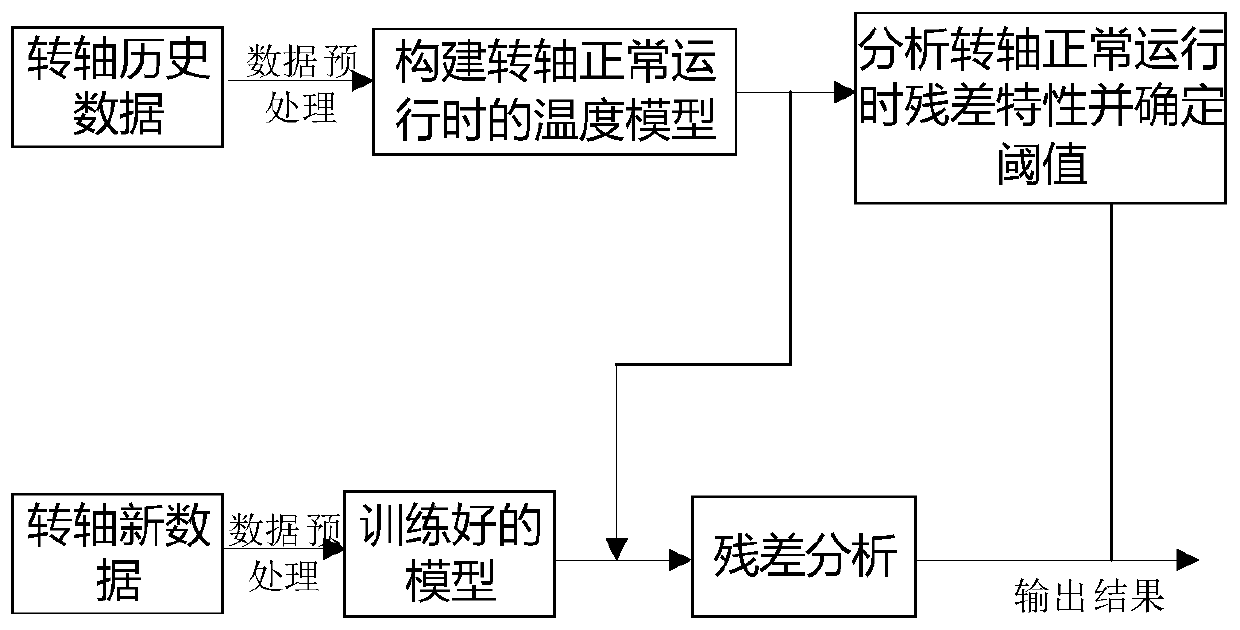
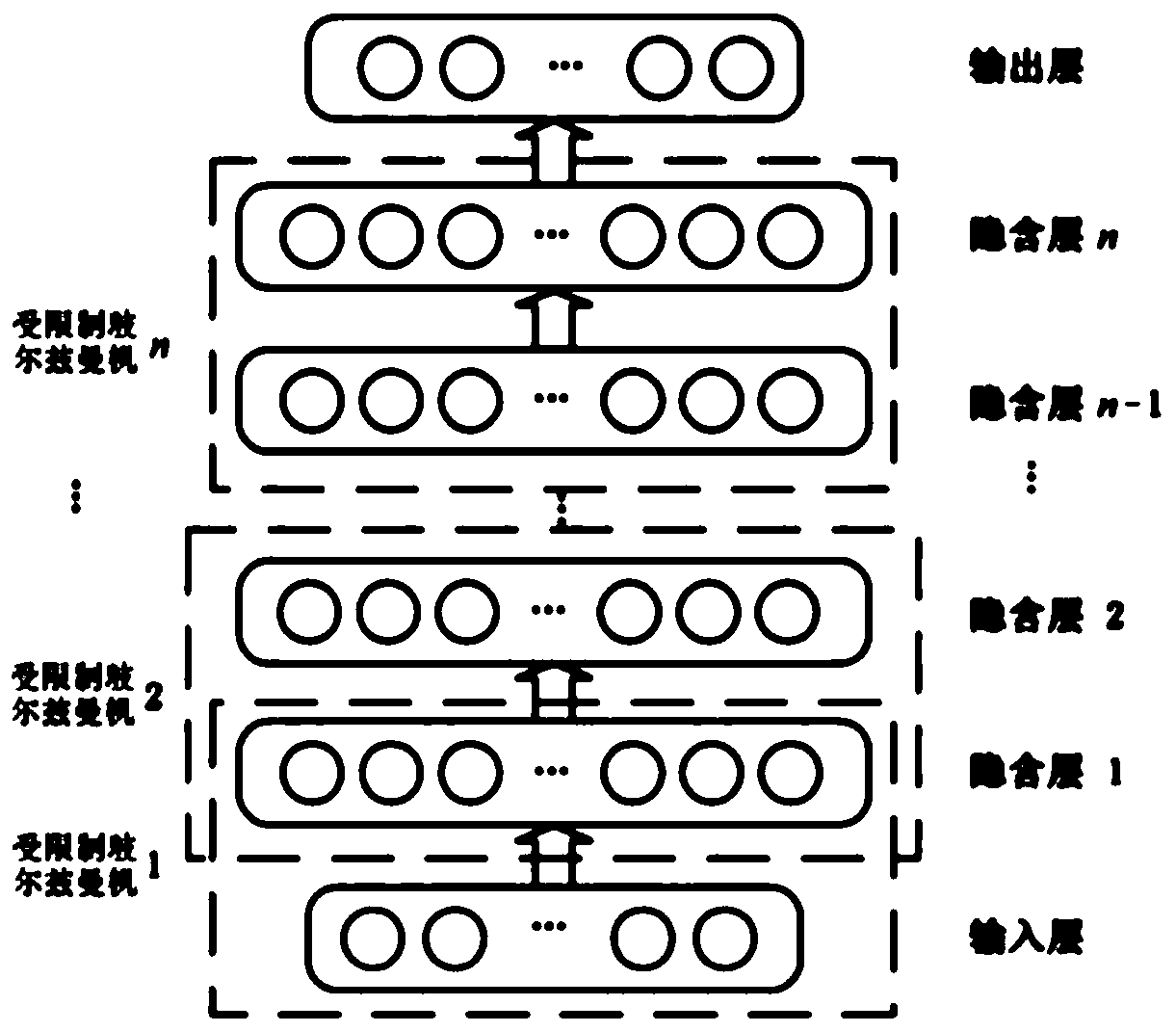
[0028] In order to facilitate those skilled in the art to understand the technical content of the present invention, the content of the present invention will be further explained below in conjunction with the accompanying drawings.

[0029] figure 1 It is a system framework diagram of the present invention. The present invention will be described in detail below according to the accompanying drawings and in combination with actual conditions. Such as figure 1 The forecasting flow chart is shown.

[0030] The historical data of the rotating shaft includes many continuous parameters such as the temperature, rotating speed and ambient temperature of the rotating shaft. Pre-train these data, and initialize the connection weights and bias values ​​between the layers of the neural network in an unsupervised greedy layer-by-layer manner. After training, after the first layer is completed, the parameters of its hidden layer are used as the second layer The input to train the seco...


PUM


Abstract

The invention relates to a water turbine rotating shaft state monitoring method and system based on a neural network. The method comprises the following steps: 1) establishing and training a neural network-based rotating shaft temperature prediction model according to historical data of the rotating shaft of the water turbine; 2) determining a fault threshold of the rotating shaft of the water turbine through a nuclear density estimation method; and 3) predicting the temperature residual distribution characteristic of the rotating shaft through the trained rotating shaft temperature predictionmodel by using the real-time data of the rotating shaft of the water turbine, and comparing the rotating shaft temperature residual distribution characteristic with the fault threshold to judge whether a fault occurs or not. According to the method, a correlation coefficient method is used for selecting parameters having certain correlation with the rotating shaft temperature for modeling, invalid values in data are removed before all correlation coefficients are calculated, smoothing and normalization processing are carried out, and an exponential weighting moving average filter is used forcarrying out smoothing processing on a residual sequence. According to the method, prediction of potential faults of the rotating shaft can be effectively achieved, and the negative effect of seriousdestructive accidents of a unit is prevented.

Description

technical field [0001] The invention belongs to the fields of artificial intelligence and hydroelectric power generation, and relates to a monitoring method, in particular to a neural network-based method and system for monitoring the state of a rotating shaft of a water turbine. Background technique [0002] With the continuous development of my country's electric power industry, hydropower energy has entered a new era of large units, UHV transmission, and intelligent control and management. On the one hand, the structural proportion of hydropower in my country's power generation supply segment is gradually increasing, and more tasks of peak regulation and frequency regulation are undertaken. As the key power generation equipment of hydropower plants, water turbines are also developing in the direction of large capacity, high specific speed, and high load. The structure and layout of its components are becoming more and more complex. The coupling effect between them is bec...

Claims


Application Information

Patent Timeline
IPC IPC(8): G06N3/04G06N3/08F03B11/00
CPCY02E10/20
Inventor 乔立中
Owner CHINA NAT SOFTWARE & SERVICE
Learn More