Permanent magnet motor rotor structure
A technology of rotor structure and permanent magnet motor, applied in the direction of magnetic circuit shape/style/structure, magnetic circuit rotating parts, etc., can solve the problems of weakening cogging torque, uneven distribution of magnetic steel, large electromagnetic vibration noise, etc. Achieve the effects of weakening cogging torque and ripple torque, improving torque density and operating efficiency, and reducing electromagnetic vibration and noise
- Summary
- Abstract
- Description
- Claims
- Application Information
AI Technical Summary
Problems solved by technology
Method used
Image
Examples
Embodiment 1
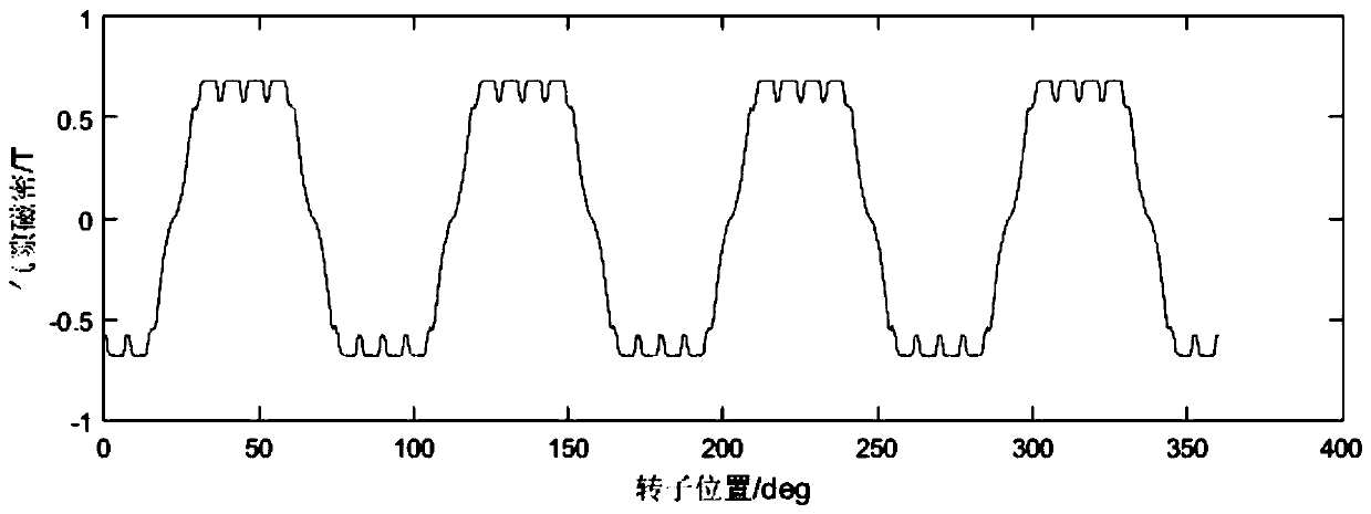
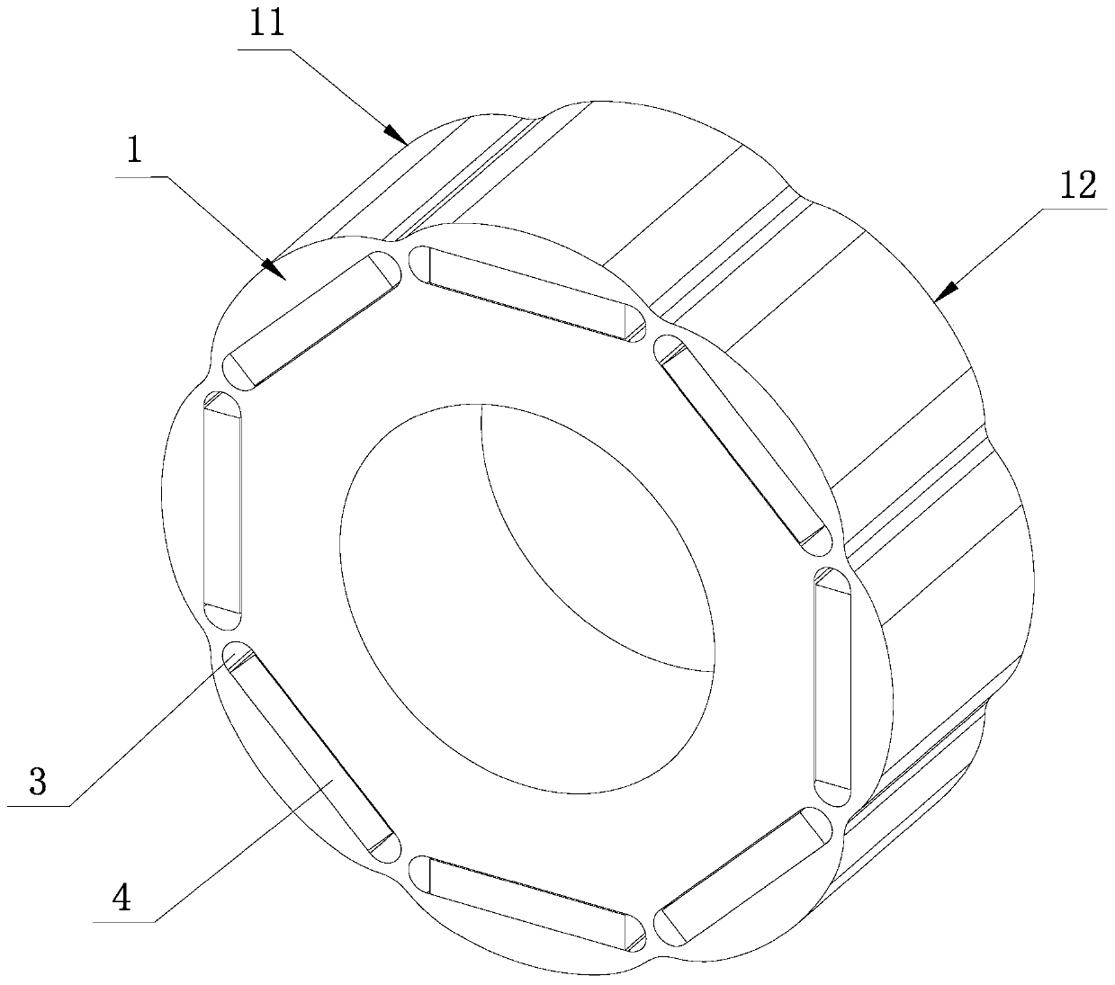
[0033] A permanent magnet motor rotor structure proposed in this embodiment, such as image 3 with Figure 4 As shown, it includes a rotor core 1. The outer edge 11 of the rotor core 1 is formed by connecting 2p identical curved surfaces 12 along the circumferential direction of the rotor core 1. Circumferential direction and connected sequentially in a symmetrical manner; wherein, p is a positive integer greater than or equal to 1, and in this embodiment, p=4, that is, 2p=8.
[0034] In this example, if Figure 4 As shown, the curved surface 12 is composed of a first arc portion 121 as the center, a second arc portion 122 symmetrically distributed on both sides of the first arc portion 121, and a symmetrical distribution on the outside of two second arc portions 122. The third arc portion 123 is connected, and the center O of the circle where the first arc portion 121 is located 1 and the center O of the circle where the second arc portion 122 is located 2 are all within ...
Embodiment 2
[0039] A permanent magnet motor rotor structure proposed in this embodiment, such as Figure 8 As shown, it includes a rotor core 1, the outer edge 11 of the rotor core 1 is formed by connecting 2p identical curved surfaces 12 along the circumferential direction of the rotor core 1, and the curved surface 12 consists of 3 segments of circular arcs and 2 segments of line segments They are sequentially connected along the circumferential direction of the rotor core 1 in a symmetrical manner; wherein, p is a positive integer greater than or equal to 1, and in this embodiment, p=4, that is, 2p=8.
[0040] In this example, if Figure 8 As shown, the curved surface 12 is composed of a first arc portion 121 as the center, a second arc portion 122 symmetrically distributed on both sides of the first arc portion 121, and a symmetrical distribution on the outside of two second arc portions 122. The line segment parts 124 are connected, and the center O of the circle where the first arc...
Embodiment 3
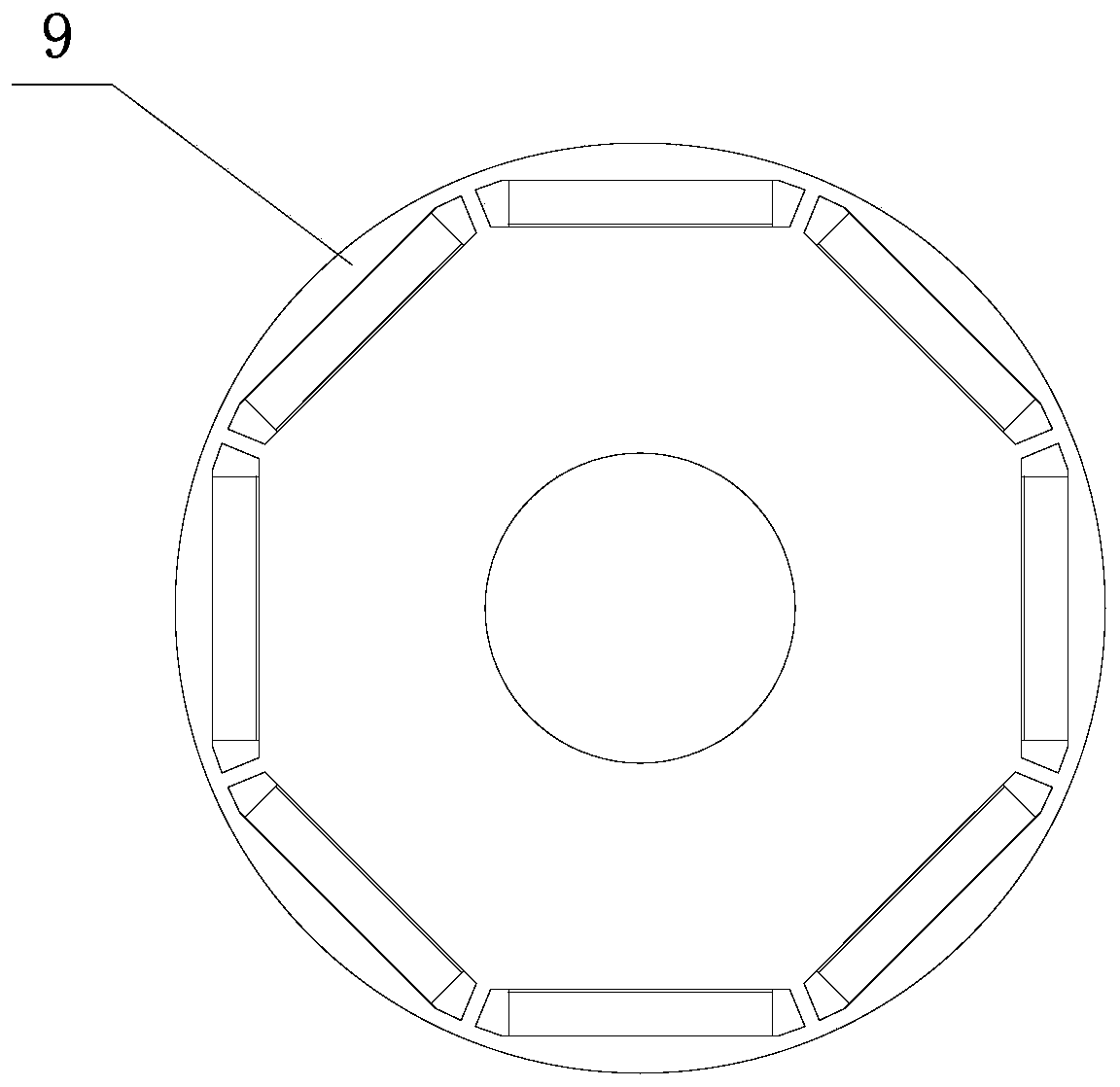
[0044] The rotor structure of a permanent magnet motor proposed in this embodiment is basically the same as that of the rotor structure of the permanent magnet motor in Embodiment 1, the difference is only in the design and layout of the magnetic steel slots of each pole, such as Figure 9 As shown, in the present embodiment, 2p (2p=8) pole magnetic steel grooves are evenly opened along the circumferential direction on the rotor core 1, and each pole magnetic steel groove corresponds to a curved surface 12, and each pole magnetic steel groove is composed of two shafts The two axial magnetic steel grooves 3 are symmetrically distributed left and right, the angle between the two axial magnetic steel grooves 3 is 180 degrees, and the symmetry axis of the two axial magnetic steel grooves 3 and the corresponding curved surface 12 The axis of symmetry X of the first circular arc portion 121 coincides with each other, and the magnetic steel 4 is installed in the axial magnetic steel s...
PUM
| Property | Measurement | Unit |
|---|---|---|
| Angle | aaaaa | aaaaa |
| Angle | aaaaa | aaaaa |
Abstract
Description
Claims
Application Information
 - R&D
- Intellectual Property
- Life Sciences
- Materials
- Tech Scout
- Unparalleled Data Quality
- Higher Quality Content
- 60% Fewer Hallucinations
Browse by: Latest US Patents, China's latest patents, Technical Efficacy Thesaurus, Application Domain, Technology Topic, Popular Technical Reports.
© 2025 PatSnap. All rights reserved.Legal|Privacy policy|Modern Slavery Act Transparency Statement|Sitemap|About US| Contact US: help@patsnap.com


