
A Beam Tracking Method for Unmanned Aerial Vehicle Millimeter Wave Communication

A drone and millimeter-wave technology, applied in radio transmission systems, diversity/multi-antenna systems, space transmit diversity, etc., can solve the problem of reduced communication rate, signal departure angle/arrival angle tracking lag or even inaccuracy, and difficulty in tracking effect and other issues, to achieve the effect of improving spectral efficiency and reducing delay error

Active Publication Date: 2020-12-04
BEIJING UNIV OF POSTS & TELECOMM
View PDF5 Cites 0 Cited by
  • Summary
  • Abstract
  • Description
  • Claims
  • Application Information

AI Technical Summary

Problems solved by technology

[0005] The existing scheme only considers the use of the position information of the sending and receiving ends or the position and attitude information of the sending end itself and the direct tracking of the signal arrival angle / departure angle, and does not consider the influence of the attitude change of the UAV movement at the sending and receiving ends. When the movement speed of the UAV is high, there may be obvious lag or even misalignment in the tracking of the signal departure angle / arrival angle, which will affect the millimeter wave beam alignment and reduce the communication rate; when the attitude of the UAV at the transceiver end changes significantly, only It is difficult to achieve a good tracking effect with the millimeter-wave beam tracking assisted by position information assistance / the transmitter's own position and attitude information, which affects the performance of millimeter-wave communication between UAVs

Method used


Image

  • A Beam Tracking Method for Unmanned Aerial Vehicle Millimeter Wave Communication
  • A Beam Tracking Method for Unmanned Aerial Vehicle Millimeter Wave Communication
  • A Beam Tracking Method for Unmanned Aerial Vehicle Millimeter Wave Communication

Examples


Embodiment Construction

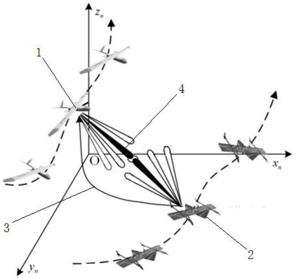
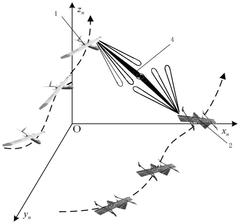
[0053] The purpose of the present invention is to use the position and attitude information of the low-frequency feedback while the sensor provides its own position and attitude information through the originating UAV, and use the machine learning method based on the Gaussian process to carry out the receiving end UAV in the future T time slots. For the prediction of position and attitude information, the corresponding coordinate transformation is carried out based on the prediction results, and the corresponding beam angle and beamforming vector are calculated by using the geometric relationship, so as to realize the high-efficiency millimeter wave beam tracking under the condition of high-speed movement and attitude change of the UAV.

[0054] Through the description of the embodiments below, the specific implementation of the present invention includes the shape, structure, mutual position and connection relationship between the various parts, the function and working princip...


PUM


Abstract

The invention discloses an unmanned aerial vehicle millimeter wave communication beam tracking method. A time slot structure of unmanned aerial vehicle millimeter wave communication is designed into an exchange time slot and T tracking time slots, and the process in the exchange time slot comprises receiving MSI feedback; Calculating an actual beamforming vector according to the actual position and attitude information of the receiving-end unmanned aerial vehicle in MSI feedback, and predicting the position and attitude information of the receiving-end unmanned aerial vehicle in T tracking time slots in the future; Transmitting information through the actual beamforming vector, Wherein the process in the tracking time slot comprises the steps of calculating a predicted beam forming vectoraccording to a predicted position and attitude information; And transmitting information through the prediction beam forming vector. The position and the posture of the unmanned aerial vehicle are effectively tracked, the millimeter wave communication spectrum efficiency of the unmanned aerial vehicle can be improved under the condition that the unmanned aerial vehicle rapidly moves, channel stateinformation feedback of pilot frequency and a receiving end is not needed, and the time delay error difference between the unmanned aerial vehicle and the real motion state can be reduced.

Description

technical field [0001] The invention relates to the technical field of millimeter-wave beam tracking of unmanned aerial vehicles, in particular to a method for tracking beams of millimeter-wave communication of unmanned aerial vehicles. Background technique [0002] mmWave beam tracking is a technique for maintaining mmWave communication links. Millimeter-wave communication uses narrow beams to compensate for the high path loss of millimeter-wave propagation, and obtains corresponding analog beamforming vectors through beam tracking technology to maintain millimeter-wave beam alignment, which can make full use of antenna array gain, maintain millimeter-wave communication links, and improve mmWave communication performance. [0003] At present, the millimeter-wave beam tracking method mainly uses auxiliary information such as position or directly tracks the signal arrival angle / departure angle. For example, in "Robust beam-tracking for mmWave mobile communications", the ext...

Claims


Application Information

Patent Timeline
Patent Type & Authority Patents(China)
IPC IPC(8): H04B7/06H04B7/08H04B7/185
Inventor 许文俊张婧琳冯志勇高晖张平张治
Owner BEIJING UNIV OF POSTS & TELECOMM
Learn More