Welding technology of ultrahigh vacuum stainless steel cavity chamber

A welding process and ultra-high vacuum technology, applied in welding equipment, welding accessories, manufacturing tools, etc., can solve the problem that the welding strength and welding sealing performance cannot meet the requirements of ultra-high vacuum, the vacuum detection is not good, and the bubbles in the welding of the chamber, etc. problems, to achieve comprehensive protection, improve protection, and reduce welding deformation

Inactive Publication Date: 2019-05-14
JIANGYIN GUANGKE PHOTOELECTRIC PRECISION EQUIP CO LTD
View PDF11 Cites 2 Cited by
  • Summary
  • Abstract
  • Description
  • Claims
  • Application Information

AI Technical Summary

Problems solved by technology

[0003] The ultra-high vacuum chamber needs to maintain a high degree of vacuum in the chamber, and in the traditional welding process of single-sided welding and double-sided forming, because the welding shielding gas is on one side of the welded part, while the welding and forming process on the back In the process, the shielding gas does not fully protect the back side, causing defects such as air bubbles and trachoma to appear on the back side of the chamber welding. The welding strength and welding sealing performance cannot meet the requirements of ultra-high vacuum. In actual use, cracks appear at the weld, and even cause serious catastrophic consequences

Method used


Image

  • Welding technology of ultrahigh vacuum stainless steel cavity chamber

Examples


Embodiment Construction

[0017] The specific implementation manners of the present invention will be further described below in conjunction with the drawings and examples. The following examples are only used to illustrate the technical solution of the present invention more clearly, but not to limit the protection scope of the present invention.

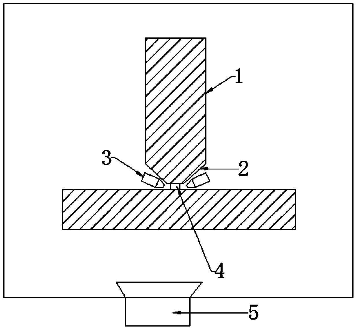
[0018] like figure 1 Shown, the present invention is a kind of welding process of ultra-high vacuum stainless steel chamber, comprises the following steps:

[0019] S1: Welding preparation, prepare welding fittings 1 according to the welding list and design drawings, prepare double-sided V-shaped grooves 2 according to the thickness of the steel plate, the top angles of the double-sided V-shaped grooves do not overlap, and the double-sided V-shaped grooves The distance between the top corners is not less than the width / thickness of the welding wire, and then remove the surface dirt on the groove and welding fittings; preheat and dry the welding wire in adv...


PUM

PropertyMeasurementUnit
lengthaaaaaaaaaa
surface roughnessaaaaaaaaaa

Abstract

The invention discloses a welding technology of an ultrahigh vacuum stainless steel cavity chamber. The welding technology of the ultrahigh vacuum stainless steel cavity chamber comprises the steps ofwelding preparation, point welding pre-positioning and synchronous welding of the inner surface and the outer surface, welding piece polishing treatment after welding and ultrasonic welding seam defect detection. According to the welding technology of the ultrahigh vacuum stainless steel cavity chamber, the joint of a dual-surface V-shaped groove is covered with a welding wire, and then synchronous dual-surface welding protected by mixed gas of dual-arc argon and helium is carried out; and the stainless steel welding quality and efficiency are improved, protecting gas generated by single-surface welding is prevented from incompletely protecting the back surface of a welding seam, the welding oxidization is reduced, the welding intensity is improved, the comprehensive protection of the gasis facilitated, and meanwhile, the welding seam strength is greatly improved due to the fact that the inner side and the outer side of a welding position are both welded, the welding quality is ensured, and the welding deformation is reduced.

Description

technical field [0001] The invention relates to the technical field of welding technology, in particular to a welding technology for an ultra-high vacuum stainless steel chamber. Background technique [0002] In terms of the division of the vacuum area, it is generally believed that in 10 -6 Under the pressure of Pa, the time for the surface of the clean sample to adsorb a single molecular layer is on the order of minutes, reaching the limit pressure of the oil diffusion pump. In turn define 10 -6 Pa to 10 -12 Pa is ultra-high vacuum, and the ultra-high vacuum chamber is a device used to provide an ultra-high vacuum environment. [0003] The ultra-high vacuum chamber needs to maintain a high degree of vacuum in the chamber, and in the traditional welding process of single-sided welding and double-sided forming, because the welding shielding gas is on one side of the welded part, while the welding and forming process on the back In the process, the shielding gas does not ...

Claims


Application Information

Patent Timeline
Patent Type & Authority Applications(China)
IPC IPC(8): B23K9/00B23K9/007B23K9/16B23K9/235B23K9/32
Inventor 瞿建强黄仕强
Owner JIANGYIN GUANGKE PHOTOELECTRIC PRECISION EQUIP CO LTD
Why Eureka
Try Eureka