Method of improving pneumatic tire vibration characteristics

A technology of pneumatic tires and tires, which is applied to the reinforcement layer of pneumatic tires, tire parts, and automobile tire testing, etc., which can solve the problems of deterioration of driving performance, reduction of tire stiffness, deterioration of steering response, etc., and achieve the effect of improving vibration behavior

Pending Publication Date: 2019-05-14
FORD GLOBAL TECH LLC
View PDF11 Cites 0 Cited by
  • Summary
  • Abstract
  • Description
  • Claims
  • Application Information

AI Technical Summary

Problems solved by technology

[0008] However, a reduction in tire stiffness, especially in the radial and/or circumferential direction (radial

Method used


Image

  • Method of improving pneumatic tire vibration characteristics
  • Method of improving pneumatic tire vibration characteristics
  • Method of improving pneumatic tire vibration characteristics

Examples


Embodiment Construction

[0058] As required, detailed embodiments of the present invention are disclosed herein; however, it is to be understood that the disclosed embodiments are merely exemplary of the invention which may be embodied in varied and alternative forms. The figures are not necessarily to scale; some features may be exaggerated or minimized to show details of particular components. Therefore, specific structural and functional details disclosed herein are not to be interpreted as limiting, but merely as a representative basis for teaching one skilled in the art to variously employ the present invention.

[0059] In the different figures, functionally equivalent parts always bear the same reference signs and are therefore usually only described once.

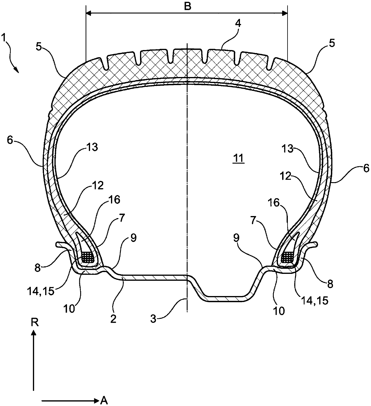
[0060] figure 1 A partial cross-sectional view of an embodiment of the pneumatic tire 1 according to the present invention is schematically shown to illustrate the general structure of the pneumatic tire 1 . The section shown is parallel ...


PUM


Abstract

A method for designing a pneumatic tire to have improved vibration characteristics. Dynamic testing of the tire detects a) respective frequencies of a plurality of radial vibration modes of the tire,and b) respective frequencies of a plurality of torsional vibration modes of the tire. The testing may determine that a first interval between the frequency of an even-numbered radial vibration mode and the frequency of an even-numbered torsional vibration mode is less than a first threshold, and/or may determine that a second interval between the frequency of an odd-numbered radial vibration modeand the frequency of an odd-numbered torsional vibration mode is less than a second threshold. One or more design parameter of the tire is/are modified to increase at least one of first interval andthe second interval to the respective first or second threshold.

Description

technical field [0001] The present invention relates to a pneumatic tire for a vehicle, and to a method for improving tire vibration characteristics to reduce noise, vibration and harshness (NVH) perceived by vehicle occupants due to tire vibration. Background technique [0002] Pneumatic tires of this type for vehicles are known in numerous embodiments and generally have a structural unit comprising at least one tread band which runs around the The main plane runs and the tread band turns on both sides of the main plane of the tire into sidewalls whose ends are respectively formed by circular / circumferential tire beads. The tread band establishes contact with the road surface during the running of the vehicle and transmits driving, braking and lateral guiding forces essentially through the sidewalls of the tire to the corresponding tire bead, which in turn has the function of ensuring a stable fixation of the tire in the connection to the Tasks on the rim of the vehicle su...

Claims


Application Information

Patent Timeline
IPC IPC(8): B60C9/02B60C9/18B60C15/04G01M17/02
CPCB60C19/002B60C99/006B60C2009/2012G01M17/025B60B2900/131B60C9/18G01H13/00G01M17/02
Inventor 阿恩·琼茨大卫·斯科特·罗威德阿恩·海登
Owner FORD GLOBAL TECH LLC
Why Eureka
Try Eureka