Rotary oscillating cutting tools for machine tools

A cutting tool and machine tool technology, applied in the field of rotary oscillating cutting tools, can solve problems such as high driving force, and achieve the effects of reducing chatter, improving rigidity, and improving processing quality

Active Publication Date: 2017-07-07
ROBERT BOSCH GMBH
View PDF14 Cites 0 Cited by
  • Summary
  • Abstract
  • Description
  • Claims
  • Application Information

AI Technical Summary

Problems solved by technology

Vibration behavior can be improved by a greater thickness of the saw blade, however this results in a higher material usage and requires higher drive forces in the manufacture of the saw blade

Method used


Image

  • Rotary oscillating cutting tools for machine tools
  • Rotary oscillating cutting tools for machine tools
  • Rotary oscillating cutting tools for machine tools

Examples


Embodiment Construction

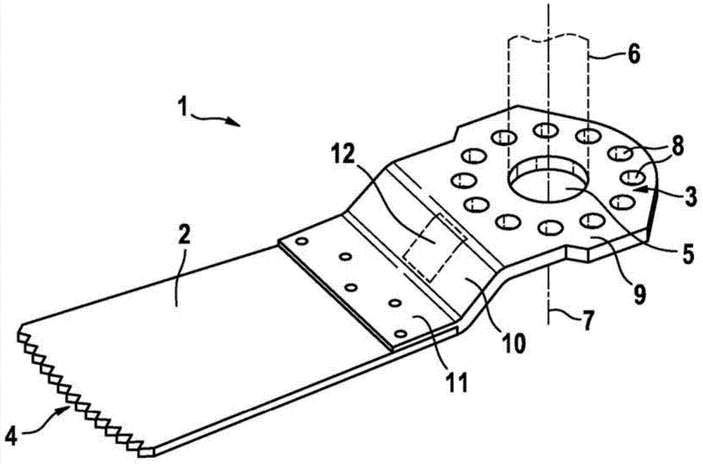
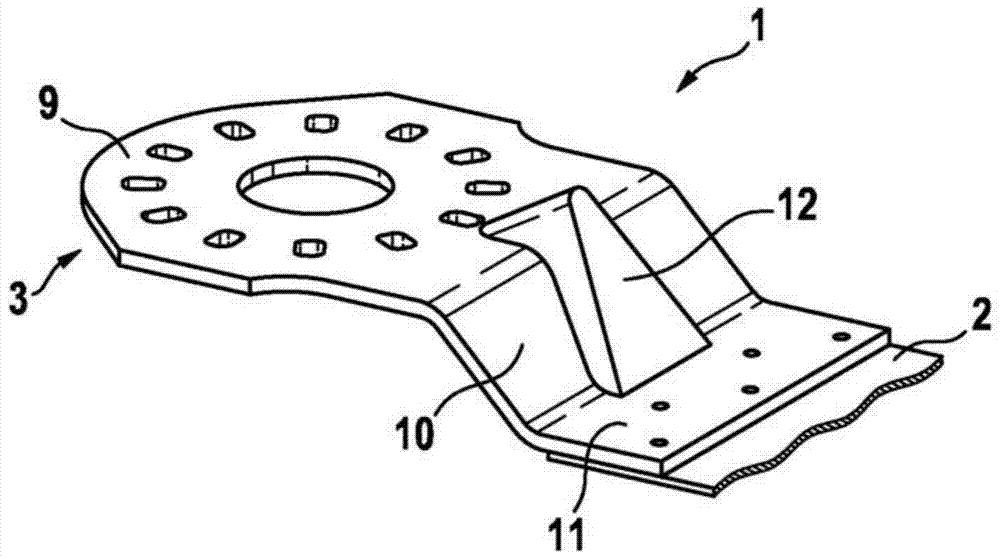
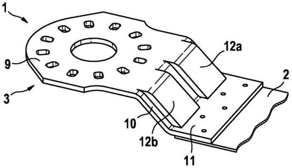
[0036] All figures show a rotary oscillating cutting tool in the form of a rotary oscillating saw blade or plunger saw blade for a power tool.

[0037] exist figure 1 The rotary oscillating cutting tool 1 shown in FIG. 2 comprises an at least substantially rectangular or arcuate stem piece 2 and a bent holder 3 connected to the stem piece 2 . On the free end side facing away from the holder 3 , the backbone piece 2 is provided with a cutting edge 4 with cutting teeth. The holder 3 comprises a shaft receptacle section 9 which has a fixed receptacle 5 for receiving a tool shaft 6 of a machine tool which performs a rotationally oscillating movement about the axis of rotation 7 . The fastening to the tool shaft 6 takes place by means of a detent opening 8 which is formed annularly around the central fastening recess 5 in the shaft receiving section 9 .

[0038] Furthermore, the holder 3 comprises a transition section 10 and a connecting section 11 via which the connection to the...


PUM


Abstract

A rotary oscillation cutting tool (1) for a machine tool has a circular-segment-shaped stem blade (2) with a working edge (4) and a holder part (3) for the holder on a shaft of the machine tool. The holder part (3) is for an improvement of rigidity next to the stem blade (2) provided with a reinforcing element (12) formed from one piece.

Description

technical field [0001] The invention relates to a rotary oscillating cutting tool for a machine tool, in particular a rotary oscillating saw blade. Background technique [0002] A number of different rotary oscillating cutting tools are known. In this case, a rotary oscillating cutting tool is to be understood in particular as a tool having a main piece, a working edge and a holder connected to the main piece for fastening to a preferably rotationally oscillating drive shaft of a power tool. In this case, the working edge is preferably provided as a cutting edge, for example with cutting teeth, cutting particles and / or cutting bodies. [0003] DE 203 08 797 U1 describes a saw blade for saws with a rotationally oscillating drive movement. The saw blade has an approximately rectangular stem blade with a cutting edge and a recess formed integrally with the stem blade and having a recess for receiving a tool shaft of a power tool. The cutting edge is implemented rectilinearly...

Claims


Application Information

Patent Timeline
Patent Type & Authority Patents(China)
IPC IPC(8): B27B19/00B23D61/00
CPCB23D61/006
Inventor H·多斯特M·博齐克
Owner ROBERT BOSCH GMBH
Why Eureka
Try Eureka