Tool arrangement

a tool and tool technology, applied in the field of tool arrangement, can solve the problem of relatively high frequency range of vibration, and achieve the effect of improving vibration behavior

Active Publication Date: 2018-08-07
KOMET GROUP GMBH
View PDF17 Cites 0 Cited by
  • Summary
  • Abstract
  • Description
  • Claims
  • Application Information

AI Technical Summary

Benefits of technology

[0003]It is therefore an object of the invention to develop a tool arrangement and a tool holder of the type mentioned at the outset in such a way that their vibration behavior is improved.

Problems solved by technology

As a result of said measure, during workpiece machining, vibrations occur in relatively high frequency ranges, with the result that they are not perceived at all or are perceived as not being unpleasant by the human ear.
In addition, the compressibility of the means for reducing the friction is not greater than the compressibility of the shank and than the compressibility of the tool holder, with the result that the tool arrangement is not compressed to a greater extent during workpiece machining, in which it is loaded with force in the axial direction, than if the flat surfaces bore directly against one another.

Method used


Image

  • Tool arrangement
  • Tool arrangement
  • Tool arrangement

Examples


Embodiment Construction

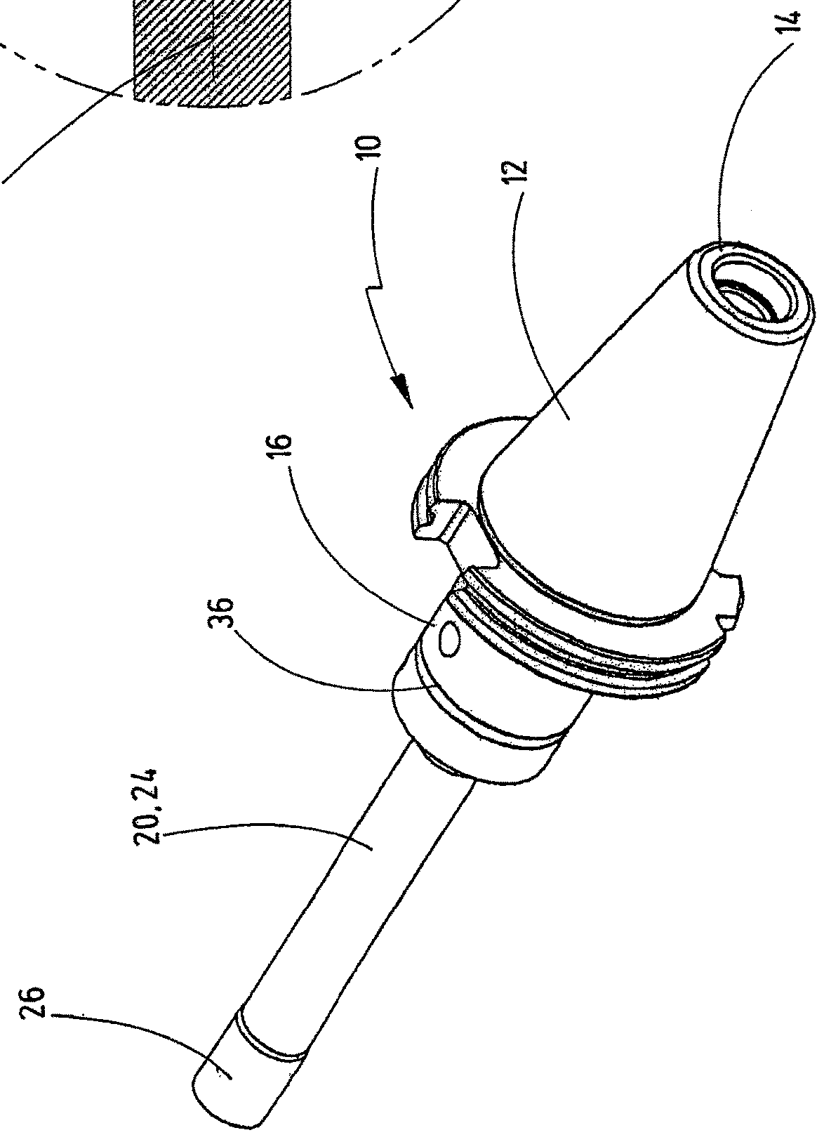
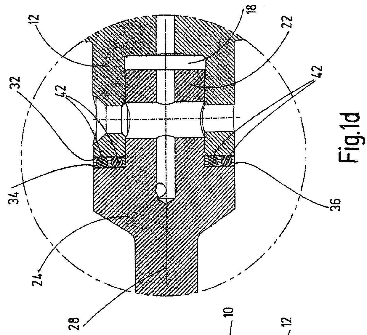
[0018]The tool arrangement 10 which is shown in FIGS. 1a to d has a tool holder 12 which is intended to be connected fixedly to a machine spindle so as to rotate with it by way of a truncated cone which extends from its one end 14, and which has a receptacle 18 as fastening means for a tool 20 at its other end 16. Of the tool 20, the drawing shows only the shank 24 which has a journal 22 which engages into the receptacle 18 and has means for fastening a tool head fixedly so as to rotate with it at the end 26 which faces away from the journal 22. The tool arrangement 10 rotates about its longitudinal center axis 28 during the machining of workpieces. In FIG. 1b, diverging coolant ducts 30 which extend through the shank 24 in the axial direction are indicated using dashed lines.

[0019]In the region of the receptacle 18 and the journal 22, the tool holder 12 and the shank 24 in each case have a circularly annular flat surface 32, 34 which extends perpendicularly with respect to the long...


PUM


Abstract

A tool arrangement containing a tool holder and a tool having a tool head for processing workpieces and a shaft supporting the tool head, wherein the tool holder and the shaft each have a planar surface oriented transversely with respect to the axial direction of the tool holder and the shaft, the planar surfaces lying opposite one another. The tool holder and the shaft are connected non-rotatably and releasably to one another by a connecting mechanism which has a journal projecting in the axial direction and a receptacle which receives the journal.

Description

FIELD OF THE INVENTION[0001]The invention relates to a tool arrangement and to a sleeve for insertion into a tool holder.BACKGROUND OF THE INVENTION[0002]Machining tools such as drilling tools which have a tool head which serves to machine workpieces and a shank which supports the tool head are connected fixedly to a tool holder so as to rotate with it, which tool holder is in turn intended to be connected fixedly to a machine spindle so as to rotate with it, with the result that the machine can transmit a rotational movement of the tool. In particular, long machining tools or tool arrangements tend to vibrate during the machining operation. Here, the vibration of the tool arrangement which is assembled from the tool and the tool holder usually takes place in frequency ranges which are unpleasant for the human ear.OBJECT OF THE INVENTION[0003]It is therefore an object of the invention to develop a tool arrangement and a tool holder of the type mentioned at the outset in such a way t...

Claims


Application Information

Patent Timeline
Patent Type & Authority Patents(United States)
IPC IPC(8): B23B31/02B23B31/00B23B31/107B23Q11/00B23C5/00B23B29/02B23B27/00
CPCB23B31/02B23B31/001B23B31/1077B23B27/002B23B29/022B23Q11/0032B23B2250/16B23B2251/70B23B2260/008B23B2260/026B23C5/003B23B2226/33
Inventor SPORS, BENNONITZSCHE, HENDRIKMAYER, MANUEL
Owner KOMET GROUP GMBH
Why Eureka
Try Eureka