Fiber Bragg Grating Demodulation System, Method and Structural Damage Monitoring System Based on Light Intensity

A fiber grating demodulation, fiber grating technology, applied in the direction of optical demodulation, optical testing flaws/defects, using optical devices to transmit sensing components, etc., can solve the problem of poor demodulation effect of high-frequency dynamic strain signals and demodulation range Narrow and other issues, to achieve the effects of no electromagnetic interference, high sensitivity, and increased accuracy

Active Publication Date: 2020-10-30
CHONGQING UNIV OF TECH
View PDF4 Cites 0 Cited by
  • Summary
  • Abstract
  • Description
  • Claims
  • Application Information

AI Technical Summary

Problems solved by technology

[0006] Aiming at the deficiencies of the above-mentioned prior art, the present invention provides a fiber grating demodulation system based on light intensity, which solves the technical problem of narrow demodulation range in the prior art, especially for the demodulation effect of high-frequency dynamic strain signals. Technical problem, it can demodulate high-frequency dynamic strain signals in the range of 1kHZ to 10MHz, which can greatly reduce the cost of demodulation system, can be free from electromagnetic interference, and can improve the accuracy of demodulation

Method used


Image

  • Fiber Bragg Grating Demodulation System, Method and Structural Damage Monitoring System Based on Light Intensity
  • Fiber Bragg Grating Demodulation System, Method and Structural Damage Monitoring System Based on Light Intensity
  • Fiber Bragg Grating Demodulation System, Method and Structural Damage Monitoring System Based on Light Intensity

Examples


Embodiment Construction

[0036] The present invention will be further described in detail below in conjunction with the accompanying drawings.

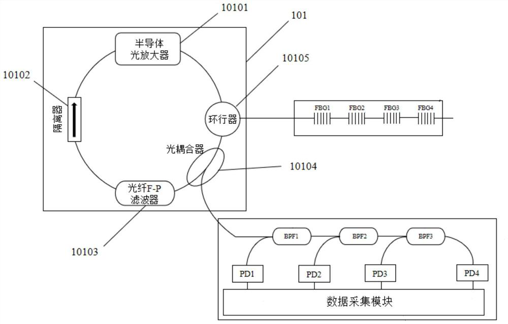
[0037] refer to figure 1As shown, a fiber grating demodulation system based on light intensity includes a semiconductor optical amplifier 10101, a circulator 10105, an optical coupler 10104, an optical fiber F-P filter 10103 and an isolator 10102 connected in sequence (the isolator 10102 ensures that the optical signal One-way transmission of 101 in the ring laser cavity), the output end of the isolator 10102 is connected to the input end of the semiconductor optical amplifier 10101, thereby forming a ring laser cavity 101 capable of loop filtering and amplifying optical signals; the semiconductor The optical amplifier 10101 can emit a light source and amplify the optical signal; the optical fiber F-P filter 10103 is a non-adjustable Fabry-Perot filter with a fixed spectrum, and the spectral range of the filter spectrum in the optical fiber F-P filter include...


PUM

PropertyMeasurementUnit
wavelengthaaaaaaaaaa

Abstract

The invention discloses a fiber Bragg grating demodulation system comprising a semiconductor optical amplifier, a circulator, an optical coupler, an optical fiber F-P filter and an isolator; the output end of the isolator is connected with the input end of the semiconductor optical amplifier, so that an annular laser cavity capable of circularly filtering and amplifying an optical signal is formed; the annular laser cavity emits a light source signal to the fiber Bragg grating via the circulator, and receives a reflected optical signal of the fiber Bragg grating; the annular laser cavity outputs a demodulated laser signal to a wavelength analysis module via the optical coupler; the wavelength analysis module is used for analyzing the moving frequency of the central wavelength of the fiberBragg grating reflectance spectrum according to the change frequency of the light intensity of the demodulated laser signal. Also disclosed is a fiber Bragg grating demodulation method based on the light intensity and a structure damage monitoring system for monitoring high-frequency dynamic strain in real time, which both adopt the demodulation system provided by the invention. According to the system and method provided by the invention, the high-frequency dynamic strain signal within the range of 1kHZ to 10MHZ can be demodulated, and the cost of the demodulation system can be greatly reduced.

Description

technical field [0001] The invention belongs to the technical field of optical fiber sensors, and in particular relates to a fiber grating demodulation system based on light intensity and a fiber grating demodulation method based on light intensity. Background technique [0002] Since the first fiber grating came out, after decades of development, the fiber grating manufacturing process has become increasingly mature, making it of great application value in the field of fiber optic sensing, and fiber grating has gradually developed into the fastest and most widely used One of the optical passive devices. [0003] All over the world, various aerospace vehicles, large offshore platforms, high-rise buildings and long-span bridges and other load-bearing structures suffer from large stress or pressure, earthquakes, floods, hurricanes, explosions and other natural or man-made disasters during their service and Long-term use will cause the reduction of mechanical parameters such a...

Claims


Application Information

Patent Timeline
Patent Type & Authority Patents(China)
IPC IPC(8): G01D5/26G01B11/16G01N21/88G02F2/00
Inventor 陶传义毛黎明廖天军冯文林
Owner CHONGQING UNIV OF TECH
Why Eureka
Try Eureka