Multi-frequency narrow-beam antenna array and antenna

A narrow beam antenna, narrow beam technology, applied in the direction of antenna array, antenna, independent antenna unit combination, etc., can solve the problem of poor wavelength convergence, and achieve the effect of excellent electrical performance and superior wavelength convergence.

Active Publication Date: 2019-05-14
WUHAN HONGXIN TELECOMM TECH CO LTD
View PDF10 Cites 10 Cited by
  • Summary
  • Abstract
  • Description
  • Claims
  • Application Information

AI Technical Summary

Problems solved by technology

[0005] One of the purposes of the present invention is to provide a multi-frequency narrow beam antenna array, which is used to solve the problem of poor c...

Method used


Image

  • Multi-frequency narrow-beam antenna array and antenna
  • Multi-frequency narrow-beam antenna array and antenna
  • Multi-frequency narrow-beam antenna array and antenna

Examples


Embodiment Construction

[0029] The specific implementation manners of the present invention will be further described in detail below in conjunction with the accompanying drawings and embodiments. The following examples are used to illustrate the present invention, but are not intended to limit the scope of the present invention.

[0030] In the description of the present invention, it should be noted that unless otherwise specified and limited, the terms "installation", "connection" and "connection" should be understood in a broad sense, for example, it can be a fixed connection or a detachable connection. Connected, or integrally connected; it can be mechanically connected or electrically connected; it can be directly connected or indirectly connected through an intermediary, and it can be the internal communication of two components. Those of ordinary skill in the art can understand the specific meanings of the above terms in the present invention in specific situations.

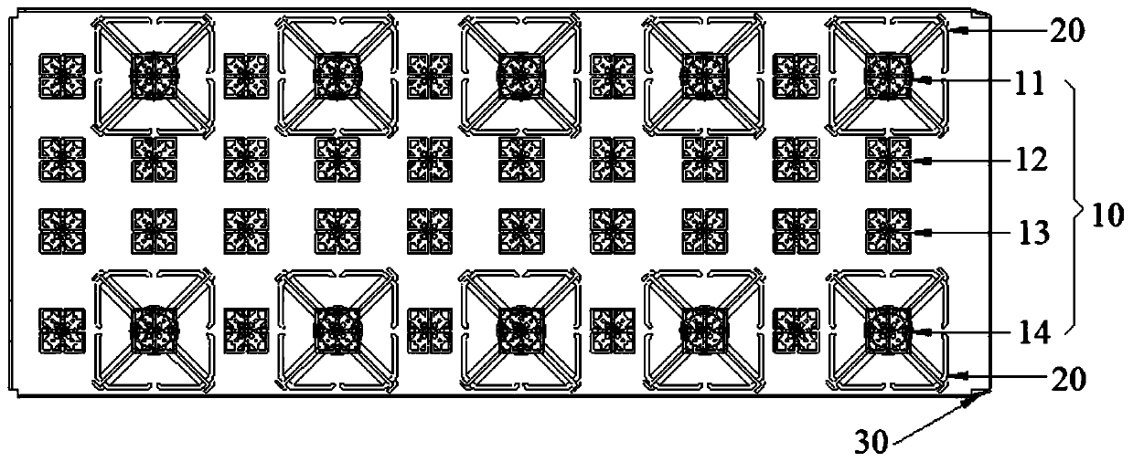
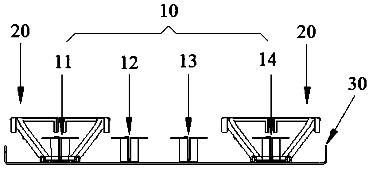
[0031] A multi-frequenc...


PUM


Abstract

The invention provides a multi-frequency narrow-beam antenna array and an antenna, and relates to the technical field of mobile communication. The multi-frequency narrow-beam antenna array comprises four columns of high-frequency arrays, wherein any two columns of the high-frequency arrays are provided with combiners at the input ends of radiation units respectively; each combiner is used for separating frequency signals of two different frequency bands from the corresponding high-frequency array, and three different frequency bands exist in the frequency signals separated by the two columns of high-frequency arrays by the combiners, wherein the two columns of the high-frequency arrays are combined by the combiners to generate same-frequency-band frequency signals which are combined to form a first high-frequency narrow-beam array; and a second high-frequency narrow-beam array and a third high-frequency narrow-beam array are formed by combining the frequency signals of two different frequency bands generated in the combining mode with the two columns of high-frequency arrays without the combiner in a one-to-one mode. According to the multi-frequency narrow-beam antenna array provided by the invention, combining is performed firstly and then merging is carried out, and the high-frequency narrow-beam arrays can achieve excellent wave width convergence and excellent electrical performance by flexibly deploying the column spacing between two adjacent columns.

Description

technical field [0001] Embodiments of the present invention relate to the technical field of mobile communications, and in particular to a multi-frequency narrow-beam antenna array and an antenna. Background technique [0002] With the continuous optimization and upgrading of mobile communication networks and the continuous advancement of high-speed rail construction, operators are increasingly paying more attention to high-speed rail network coverage scenarios, and the most suitable antenna for high-speed rail network coverage is a narrow beam antenna. Common narrow-beam antennas are mostly single-band or purely high-frequency or purely low-frequency, which is neither in line with the construction idea of ​​multi-system co-construction antenna, but also wastes high-speed rail station resources to a certain extent. [0003] At present, when the multi-band narrow beam antenna array uses four columns of arrays to synthesize three columns of narrow beam arrays, the general tech...

Claims


Application Information

Patent Timeline
IPC IPC(8): H01Q21/00H01Q21/30H01Q1/36H01Q1/50H01Q19/17
Inventor 郑明杰孙彦明黄梓璨
Owner WUHAN HONGXIN TELECOMM TECH CO LTD
Why Eureka
Try Eureka