Stamping die

A technology for stamping dies and die bases, which is applied in the direction of perforating tools, forming tools, manufacturing tools, etc., can solve the time-consuming and labor-intensive problems of the loading tank, and achieve the effect of improving cleaning efficiency and improving cleaning efficiency

Active Publication Date: 2019-05-17
PHNIX GUANGZHOU ELECTRICAL
View PDF9 Cites 6 Cited by
  • Summary
  • Abstract
  • Description
  • Claims
  • Application Information

AI Technical Summary

Problems solved by technology

[0003] Based on this, it is necessary to solve the problem of not cleaning the loading tank in the stamping die and the time-consuming and laborious cleaning of the loading tank. Cleaning of the material tank and the washed away workpieces is convenient for recycling and reuse of the washed away workpieces, and it also avoids manual cleaning of the load tank

Method used


Image

  • Stamping die
  • Stamping die
  • Stamping die

Examples


Embodiment 1

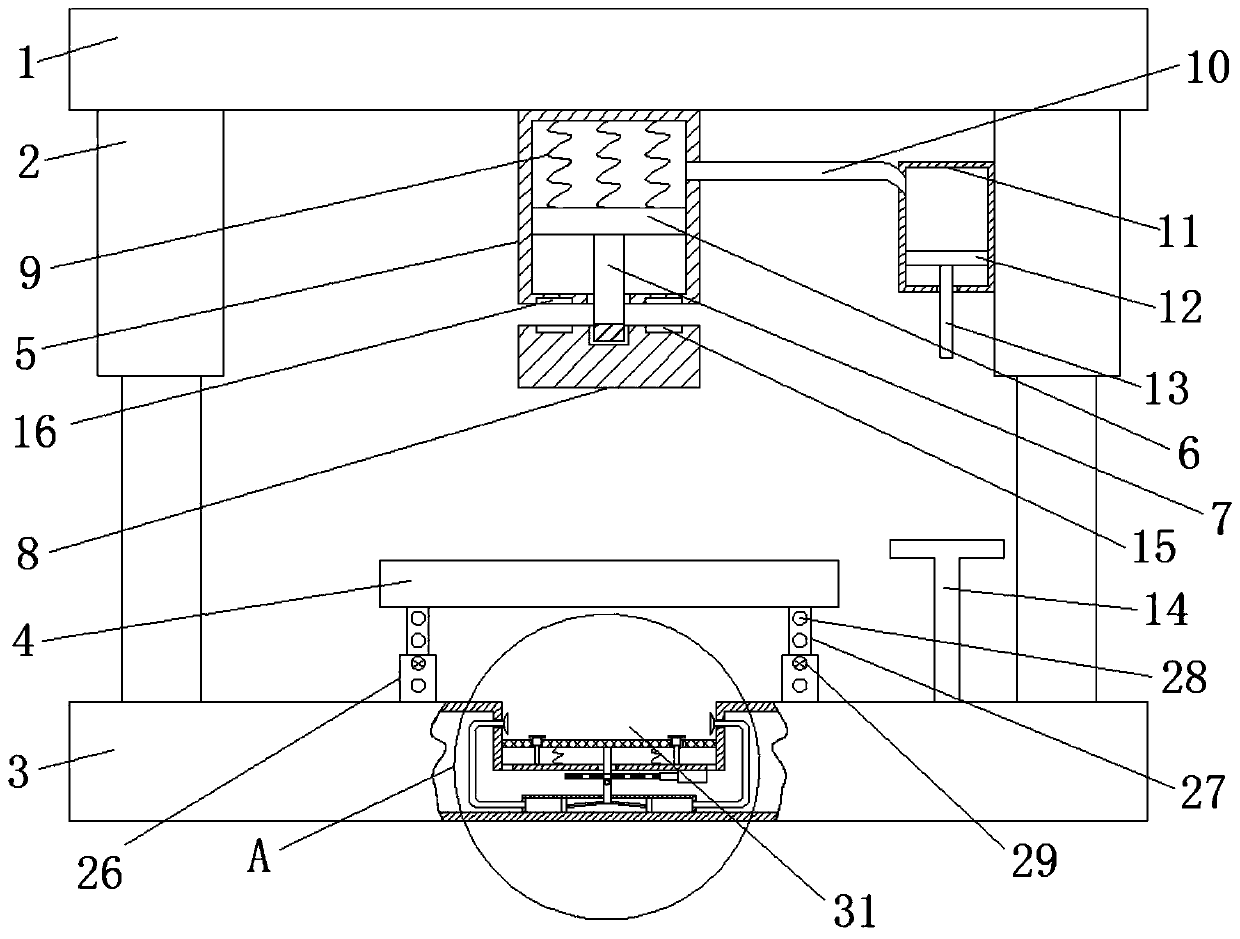
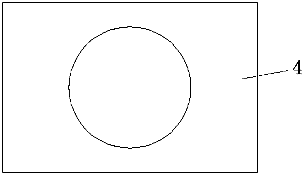
[0045] refer to Figure 1-3 , a stamping die, including an upper mold base 1, a lower mold base 3, a core plate 4 and a punch mechanism. The lower mold base 3 is connected with the upper mold base 1 through two guide columns 2 . Loading trough 32 is used to carry the workpiece that is washed away; Offer the model hole that is used for forming on the mold core plate 4 such as figure 2 As shown, and there are positioning pins on the core plate 4, which are not shown in the figure. Use positioning pins to locate the position of the workpiece. The mold core plate 4 is installed on the lower mold base 3 .

[0046] Wherein, the punch mechanism includes a sleeve one 5, a piston one 6, a push rod one 7, a movable punch 8, a sleeve two 11, a piston two 12, a push rod two 13 and a T-shaped support plate 14.

[0047] The sleeve one 5 is installed on the upper mold base 1; the piston one 6 is slidably installed inside the sleeve one 5. The upper end surface of the piston one 6 is co...

Embodiment 2

[0054] After the stamping die in Example 1 is used for a long time, the punch part is easily damaged and needs to be replaced. However, in the prior art, it is cumbersome to replace the punch and also wastes resources. For this, we must improve on this. The specific improvement plan is as follows:

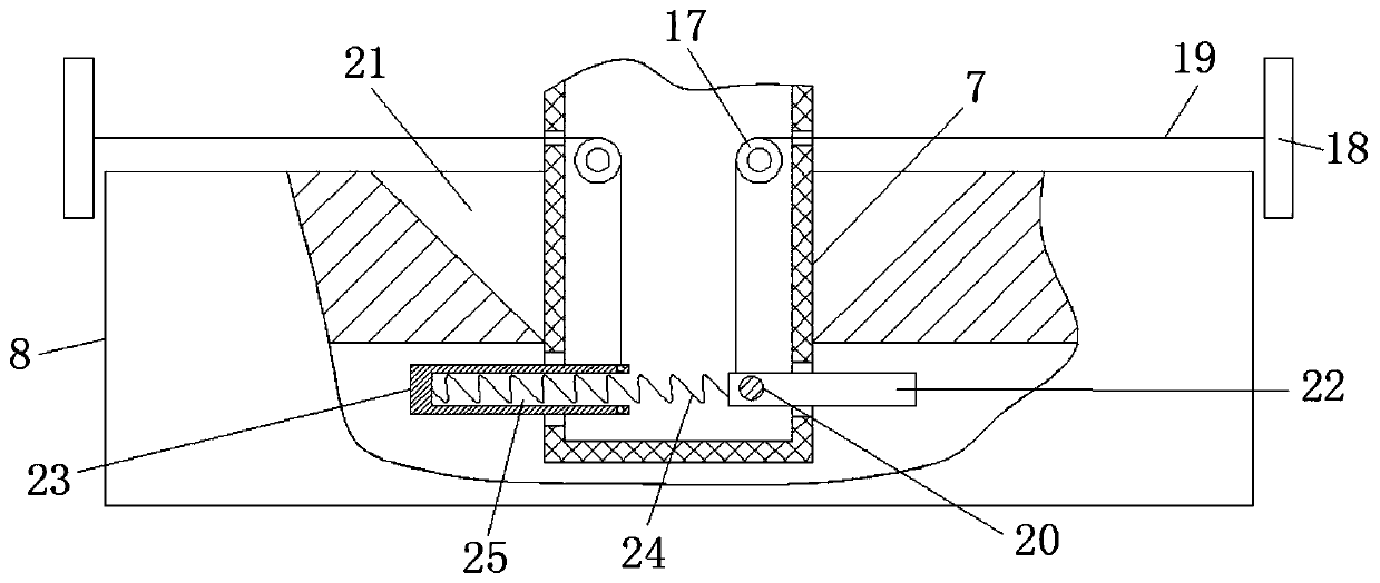
[0055] refer to figure 1 and image 3 , the other end of movable punch 8 and push rod one 7 is detachably connected. There are two schemes for the detachable connection, for those skilled in the art to refer to.

[0056] Option 1: The other end of the push rod 7 is provided with an external thread. The movable punch 8 is provided with an internal thread groove corresponding to the external thread. Push rod one 7 is connected with movable punch 8 by threads such as figure 1 shown.

[0057] Option two: the push rod one 7 and the movable punch 8 are both hollow structures. The top of the movable punch 8 is provided with a wedge-shaped hole 21, and the movable punch 8 is provi...

Embodiment 3

[0062] When utilizing the stamping die in embodiment 1 and embodiment 2 to carry out punching, the workpiece that is punched off falls directly on the lower mold base 3 . Can cause the lubricating oil splash on the workpiece that is washed away like this, pollute the table top of lower mold base 3. It is relatively laborious to clean the table top of the lower mold base 3 . To this end, we make the following improvements:

[0063] refer to Figure 4-5 , Stamping die, comprise lower mold base 3, slide plate 32, energy storage spring 33, blocking mechanism 35, U-shaped cover 37, two sliders 38, two connecting rods 39, iron rod two 310, two infusion tubes 312, Two tent heads 313, an electric push rod 314, a moving plate 315 and a permanent magnet one 316.

[0064] Wherein, the lower mold base 3 is a hollow structure, and the lower mold base 3 is provided with a loading groove 31 . The loading trough 31 is used to collect the washed workpieces in a concentrated manner. At lea...


PUM


Abstract

The invention relates to a stamping die. The stamping die comprises a lower die base, a sliding plate, an energy storage spring, a blocking mechanism, a U-shaped cover, two sliding blocks, two connecting rods, a second iron rod, two infusion tubes, two awning heads, an electric push rod, a movable plate and a first permanent magnet. According to the stamping die, a formed object carrying groove isused for intensively collecting a punched workpiece, so that the table surface of the lower die base is prevented from being polluted by the washed workpiece. A first iron rod and a second iron rod are attracted intermittently by utilizing the first permanent magnet. By means of the vertical movement of the second iron rod, the sliding blocks move back and forth, and cleaning liquid is extruded,so that the effect of automatic cleaning is achieved, and time and labor are not wasted. In addition, a sliding plate moves up and down through the first iron rod and enables the sliding plate to vibrate under the action of an energy storage spring. The contact frequency between the cleaning liquid and the washed workpiece is increased by using the tremor of the sliding plate. Under the action ofthe blocking mechanism, a dual cleaning program for soaking and rinsing the washed workpiece is achieved through the cleaning liquid, and the cleaning efficiency of the cleaning liquid is further improved.

Description

technical field [0001] The invention relates to the technical field of stamping dies, in particular to stamping dies. Background technique [0002] Stamping die is a special process equipment for processing materials (metal or non-metal) into parts (or semi-finished products) in cold stamping processing, called cold stamping die (commonly known as cold stamping die). Stamping is a pressure processing method that uses a mold installed on a press to apply pressure to the material at room temperature to cause separation or plastic deformation to obtain the required parts. According to the nature of the process, stamping dies can be divided into punching dies, bending dies, drawing dies and forming dies. Before using the stamping die, it is necessary to apply lubricating oil to the parts of the stamping die to reduce the wear of the stamping die. In this way, when the workpiece is stamped, the washed workpiece is accompanied by lubricating oil, which needs to be processed befo...

Claims


Application Information

Patent Timeline
Patent Type & Authority Applications(China)
IPC IPC(8): B21D28/34B21D37/04B21D43/20B08B3/02B08B3/08B26F1/14B26D7/00B26D7/26B26D7/27
Inventor 柏先宁何强杨超毅
Owner PHNIX GUANGZHOU ELECTRICAL
Why Eureka
Try Eureka