A self-feeding continuous cutting device for steel pipes

A cutting device and self-feeding technology, which is applied in the direction of pipe shearing device, shearing device, and accessory device of shearing machine, etc., can solve the problems of low degree of automation and high labor intensity

Active Publication Date: 2021-08-24
CHANGCHUN JINJIANG AUTO PARTS
View PDF0 Cites 0 Cited by
  • Summary
  • Abstract
  • Description
  • Claims
  • Application Information

AI Technical Summary

Problems solved by technology

[0003] After the finished steel pipe is produced, it is often cut according to the needs to facilitate transportation and installation. Most of the existing steel pipe cutting is carried out by a manual cutting machine. Manually hold the handle of the cutting machine and press the handle to make the cutting machine cut the steel pipe at the bottom, which is automated. Low degree, high labor intensity

Method used


Image

  • A self-feeding continuous cutting device for steel pipes
  • A self-feeding continuous cutting device for steel pipes
  • A self-feeding continuous cutting device for steel pipes

Examples


Embodiment 1

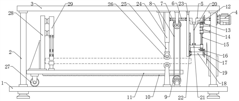
[0023] see Figure 1~3 , in an embodiment of the present invention, a self-feeding continuous cutting device for steel pipes includes a base plate 1, a crankshaft 5, a residual gear 9, a workbench 11, a cutter 19, a clamping wheel 26 and a fixing device 29; above the base plate 1 Side plates 2 are respectively fixed on both sides, and a top plate 3 is fixed above the side plates 2, wherein a driving motor 4 is fixedly installed on one side of the side plate 2 through a flange. Through the side plate 2 and connected with the bearing in rotation, the driving motor 4 wire is connected to the power supply and the switch, and the switch is activated to make the driving motor 4 energized to drive the crankshaft 5 to rotate; the crankshaft 5 is fixedly connected to the worm 6, and the bearing at the end of the worm 6 is connected to the hydraulic pressure. The side wall of the cylinder 24, the upper end of the hydraulic cylinder 24 is fixed on the top plate 3 through reinforcing ribs...

Embodiment 2

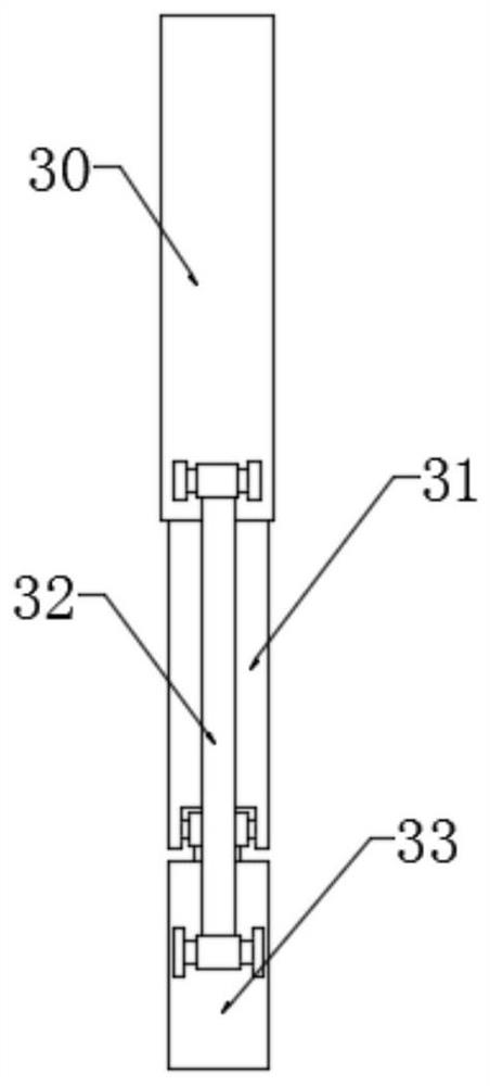
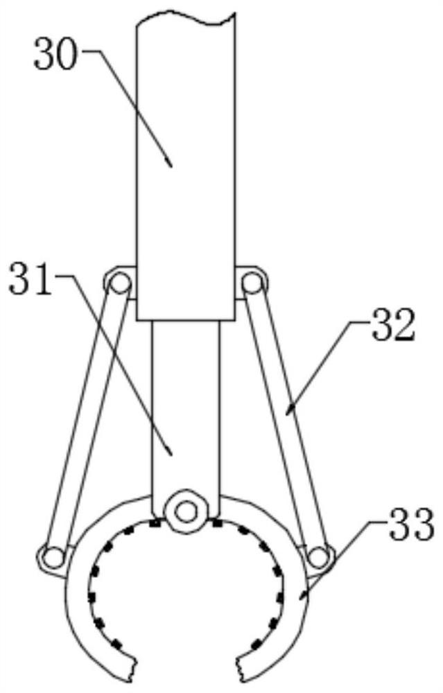
[0027] In order to further explain the above-mentioned self-feeding continuous cutting device for steel pipes, this application provides another embodiment. The self-feeding continuous cutting device for steel pipes in this embodiment has the following technical features: the workbench 11 is fixedly connected to There is a tail plate 28, and the side wall of the tail plate 28 is provided with a fixing device 29. Specifically, the fixing device 29 includes a cylinder 30, a piston rod 31, a drive rod 32 and a claw 33, wherein the cylinder 30 is fixed on the tail plate 28, The bottom of the cylinder 30 is slidingly connected to the piston rod 31, and the two sides of the lower end of the piston rod 31 are respectively rotated to connect with the claws 33. The middle part of the claw 33 is connected to the two sides below the cylinder 30 through the drive rod 32, and the cylinder 30 is used to drive the piston rod 31 to move up and down to drive The driving rod 32 drives the claw 3...


PUM


Abstract

The invention discloses a self-feeding continuous cutting device for steel pipes, in particular to a device capable of automatically feeding and cutting steel pipes. The device drives a connecting rod through a crankshaft to drive a beam and a sliding plate to reciprocate and move up and down to drive a telescopic rod. And the driven shaft moves up and down, and the crankshaft that rotates at the same time uses the bevel gear set to drive the driven shaft to rotate, so as to realize the reciprocating up and down rotation of the tool and continuous cutting, and a rack is set under the workbench, and the worm gear is driven by the worm to rotate and then drive The residual gear rotates to realize the intermittent movement function of the rack and the workbench; the top plate is fixed above the side plate, and the drive motor is fixedly installed on one side plate through a flange, and the output end of the drive motor is connected to the crankshaft in rotation, and the crankshaft is fixedly connected to the worm, and the worm The end bearing is rotatably connected to the side wall of the hydraulic cylinder, and a worm gear is meshed under the worm, and the worm gear is connected to the residual gear through a synchronous belt; the toothed part of the residual gear is engaged with the rack, and the rack is fixed under the workbench.

Description

technical field [0001] The invention relates to a mechanical processing and cutting equipment, in particular to a self-feeding continuous cutting device for steel pipes. Background technique [0002] Steel pipes are very common in production and life. Steel pipes are not only used to transport fluids and powdery solids, exchange heat, and manufacture mechanical parts and containers. It is also an economical steel. Using steel pipes to manufacture building structure grids, pillars and mechanical supports can reduce weight, save 20-40% of metal, and realize factory-like mechanized construction. The use of steel pipes to manufacture highway bridges can not only save steel and simplify construction, but also greatly reduce the area of ​​the protective layer, saving investment and maintenance costs. [0003] After the finished steel pipe is produced, it is often cut according to the needs to facilitate transportation and installation. Most of the existing steel pipe cutting is c...

Claims


Application Information

Patent Timeline
Patent Type & Authority Patents(China)
IPC IPC(8): B23D21/00B23D33/00B23D33/02
Inventor 戎珊珊
Owner CHANGCHUN JINJIANG AUTO PARTS
Why Eureka
Try Eureka