
Manipulator lifting and rotating connecting structure

A technology of connecting structure and manipulator, applied in the field of medical devices, can solve the problems of difficulty in installation adjustment and post-maintenance, large cross-sectional size of rectangular or square tubes, large space for counterweight, etc., achieving compact structure, improving rigidity and motion accuracy, space saving effect

Pending Publication Date: 2019-05-17
CHONGQING JINSHAN MEDICAL ROBOTICS CO LTD
View PDF9 Cites 0 Cited by
  • Summary
  • Abstract
  • Description
  • Claims
  • Application Information

AI Technical Summary

Problems solved by technology

For this structure, if full counterweight is required, a large counterweight space is required, resulting in a larger cross-sectional size of the rectangular tube or square tube to be selected.
A ball screw is installed inside a square tube or a rectangular tube as a driving device. The screw nut structure of this mechanism is enclosed inside the square tube. The structure is compact and saves space to a large extent, but it still seems top-heavy The modular screw nut structure is difficult to install, adjust and maintain in the later period. The four directions of the column bear the same moment, without highlighting the key points, and there is still a certain degree of waste

Method used


Image

  • Manipulator lifting and rotating connecting structure
  • Manipulator lifting and rotating connecting structure
  • Manipulator lifting and rotating connecting structure

Examples


Embodiment Construction

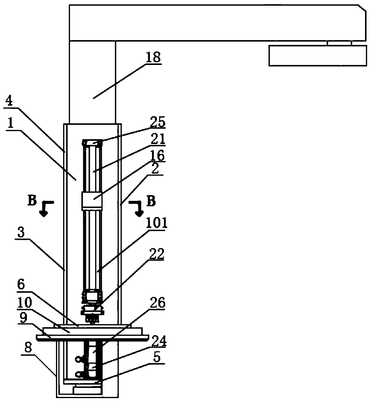
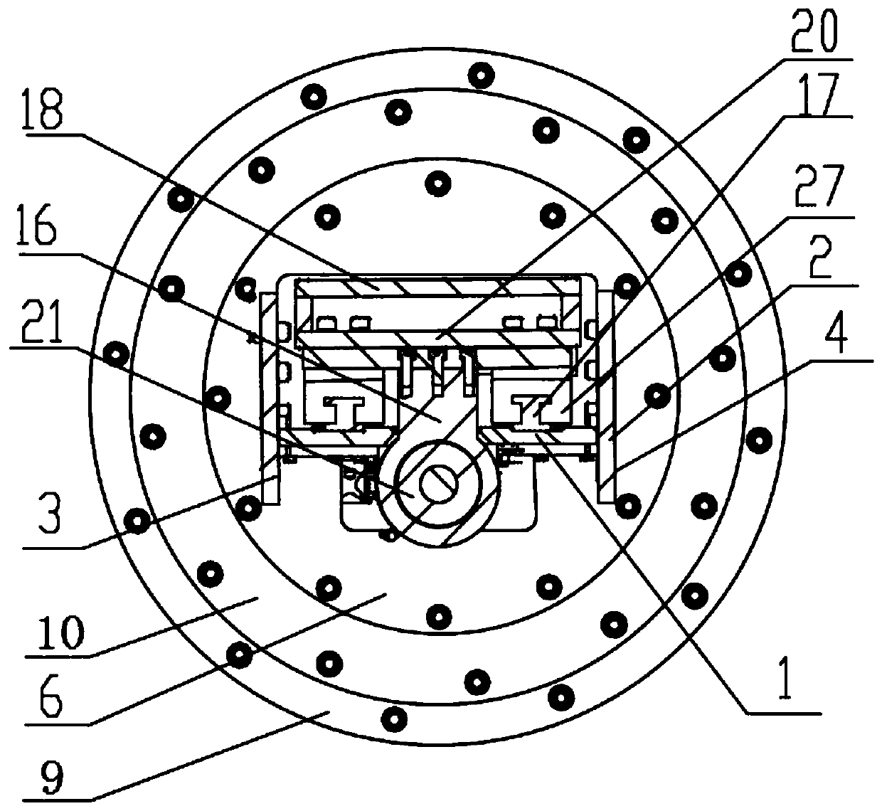
[0017] The structural features of each part of the present invention will be described in detail below, and if there is a description to the direction (up, down, left, right, front, back), it is based on figure 1 and 2 The shown structure is a reference description, but the actual use direction of the present invention is not limited thereto. Below in conjunction with accompanying drawing and embodiment the present invention will be further described:

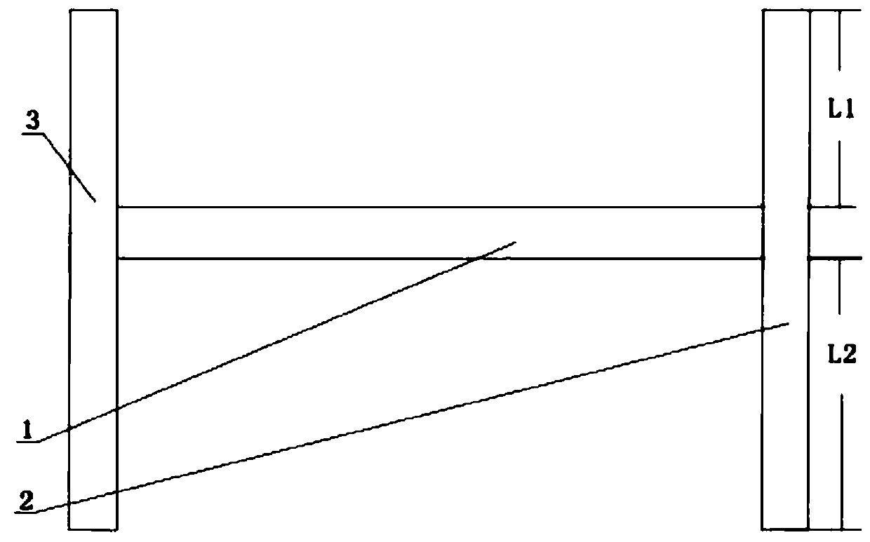
[0018] Such as figure 1 and image 3 As shown, the embodiment of the present invention discloses a manipulator lifting and turning connection structure, including a column 4, a lifting mechanism and a driving mechanism; the column 4 is I-shaped, and the column 4 is provided with a chute 101; the chute 101 is provided with a connecting block 16 and the two ends of connecting block 16 stretch out chute 101, and one end of connecting block is connected with lifting mechanism, and the other end is connected with driving mechanis...


PUM


Abstract

The invention discloses a manipulator lifting and rotating connecting structure. The manipulator lifting and rotating connecting structure comprises a standing column, a lifting mechanism and a driving mechanism, the standing column is I-shaped, a sliding groove is formed in the standing column, a connecting block is connected within the sliding groove, the two ends of the connecting block extendout of the sliding groove, one end of the connecting block is connected with the lifting mechanism, and the other end of the connecting block is connected with the driving mechanism. The manipulator lifting and rotating connecting structure achieves the improvement of the rigidity of the system.

Description

technical field [0001] The invention relates to the field of medical equipment, in particular to a lifting and turning connection structure of a manipulator. Background technique [0002] Minimally invasive surgical robots can reduce the physical labor of doctors during surgery while achieving the purpose of precise surgery. At present, the minimally invasive surgical robots on the market are mainly products of Intuitive Surgical Company of the United States. Its minimally invasive surgical robots are divided into three parts: video cart, surgical trolley and console. The surgical trolley has structures such as bases and columns. In addition, the research and development products of some companies also adopt the form of base and column. Among them, the main structural forms of the column part of the trolley include: closed column and outer drive structure, closed column and counterweight structure, and installation of balls inside square or rectangular tubes. The screw acts...

Claims


Application Information

Patent Timeline
Patent Type & Authority Applications(China)
IPC IPC(8): B25J17/00
Inventor 王了王勇柳维强
Owner CHONGQING JINSHAN MEDICAL ROBOTICS CO LTD
Learn More