Glass ceramic composition, glass ceramic sintered body, and multilayer ceramic electronic device

a technology of glass ceramic and electronic device, applied in the direction of fixed capacitor electrodes, solid-state devices, fixed capacitors, etc., can solve the problem that the multi-layer ceramic electronic device itself is also required to have a high flexural strength, and achieves low relative dielectric constant, high qf value, and superior chemical stability

Active Publication Date: 2010-02-25
MURATA MFG CO LTD
View PDF33 Cites 44 Cited by
  • Summary
  • Abstract
  • Description
  • Claims
  • Application Information

AI Technical Summary

Benefits of technology

[0034]According to the glass ceramic composition of the present invention, firing can be performed at a temperature of 1,000° C. or less, and the glass ceramic sintered body obtained by this firing has superior chemical stability, a relatively low relative dielectric constant, a high Qf value, and a stable temperature coefficient (τf) of resonant frequency.
[0035]When a multilayer ceramic electronic device is formed using the glass ceramic sintered body of the present invention, copper or silver can be used as a primary component of wiring conductors included in the electronic device, and as a result, a multilayer ceramic electronic device preferably used for high frequency applications can be formed.
[0036]Since the borosilicate glass powder included in the glass ceramic composition of the present invention contains at least one of calcium oxide, barium oxide, and strontium oxide as an additive component, the electrical insulating reliability of a glass ceramic sintered body obtained by firing can be improved. Although not being exactly understood, the mechanism of improving the insulating reliability has been conceived as follows.
[0037]The glass ceramic sintered body of the present invention basically includes a Mg2SiO4 crystal phase of the first ceramic powder and an Mg—Si—B—Zn—Li-based glass phase of the borosilicate glass powder and also has a fine structure in which a Li2(Mg,Zn)SiO4-based crystal phase is precipitated in the Mg—Si—B—Zn—Li-based glass phase. In this glass ceramic sintered body, for example, when TiO2 is contained as the second ceramic powder, crystal phases of MgTiO3 and MgTi2O5 are further precipitated, and it has been conceived that an AB2O5 type crystal phase, such as MgTi2O5, causes degradation in insulating reliability. Accordingly, when Ca, Ba, and / or Sr is added beforehand to the glass phase, the above element reacts with TiO2 to form an ABO3 type crystal phase, such as CaTiO3, BaTiO3, or SrTiO3, so that the AB2O5 type crystal phase is not likely to be formed. That is, since the ABO3 type crystal phase, such as CaTiO3, BaTiO3, or SrTiO3, is precipitated preferentially to the AB2O5 type crystal phase, such as MgTi2O5, as a result, precipitation of the AB2O5 type crystal phase, such as MgTi2O5, is suppressed, so that the degradation in insulating reliability is suppressed.
[0038]Accordingly, when a multilayer ceramic electronic device is formed using the glass ceramic sintered body of the present invention, the thicknesses of glass ceramic layers included therein can be decreased.
[0039]In addition, since the glass ceramic composition of the present invention includes the fourth ceramic powder containing SrZrO3 as a primary component, the crystallinity degree of a glass ceramic sintered body obtained by firing the above glass ceramic composition can be improved, and hence the flexural strength of the glass ceramic sintered body can be improved. Accordingly, when a multilayer ceramic electronic device is formed using the glass ceramic sintered body of the present invention, the thickness of the multilayer ceramic capacitor can be advantageously decreased.

Problems solved by technology

In addition, concomitant with the decrease in thickness of the multilayer ceramic electronic device, the multilayer ceramic electronic device itself is also required to have a high flexural strength.

Method used


Image

  • Glass ceramic composition, glass ceramic sintered body, and multilayer ceramic electronic device
  • Glass ceramic composition, glass ceramic sintered body, and multilayer ceramic electronic device
  • Glass ceramic composition, glass ceramic sintered body, and multilayer ceramic electronic device

Examples


experimental example 1

[0138]First, as a borosilicate glass powder contained in a glass ceramic composition, various compositions shown in Table were prepared.

TABLE 1Li2OMgOBaOCaOSrOB2O3SiO2ZnO[PERCENT[PERCENT[PERCENT[PERCENT[PERCENT[PERCENT[PERCENT[PERCENTGLASSBYBYBYBYBYBYBYBYMARKWEIGHT]WEIGHT]WEIGHT]WEIGHT]WEIGHT]WEIGHT]WEIGHT]WEIGHT]REMARKG1*2282.501520257.5G23272.501520257.5G31522.52.501017.5257.5G4*1621.52.501017.5257.5G5*517.5002025257.5G65200017.525257.5G7*55000517.5157.5G855050017.5157.5G955005017.5157.5G1055012217.5157.5G11*552.5002.517.5157.5DEVITRIFICATIONG12*5312.501514257.5DEVITRIFICATIONG135302.501515257.5G145252.501030207.5G15*5242.501031207.5G16*5412.50152097.5DEVITRIFICATIONG175402.501520107.5G18522.52.501017.5357.5G19*521.52.501017.5367.5G20*527.52.501520255G21526.52.501520256G225252.50517.52520G23*5242.50517.52521G24*521.5260020207.5G25517.5250020257.5G265302.501520207.5G27*526.5016020257.5G28527.5015020257.5G2952502.51520257.5G30*521.5002620207.5G31517.5002520257.5G325251052.520257.5G3...

experimental example 2

[0169]Experimental Example 2 was carried out in order to confirm the superiority of SrZrO3 forming the fourth ceramic powder. More particularly, Sample 44 formed in Experimental Example 1 was used as a sample within the range of the present invention, and by using this sample as the reference, the superiority of SrZrO3 was confirmed. Hence, as the fourth ceramic powder, besides a SrZrO3 powder having an average particle diameter of 0.5 μm, an Al2O3 powder having an average particle diameter of 0.5 μm was also prepared.

[0170]Next, in order to obtain a glass ceramic composition of each sample in accordance with Table 4 by using Glass G33 shown in the Table 1, the first ceramic powder, the borosilicate glass powder, the second ceramic powder, the third ceramic powder, and the fourth ceramic powder were mixed together.

TABLE 4AMOUNTAMOUNTOF FIRSTSECOND CERAMICOF THIRDCERAMICGLASSSrTiO3TiO2CERAMICFOURTH CERAMIC(Mg2SiO4)AMOUNTAMOUNTAMOUNT(BaZrO3)TYPEAMOUNT(PERCENT(PERCENT(PERCENT(PERCENT(P...

experimental example 3

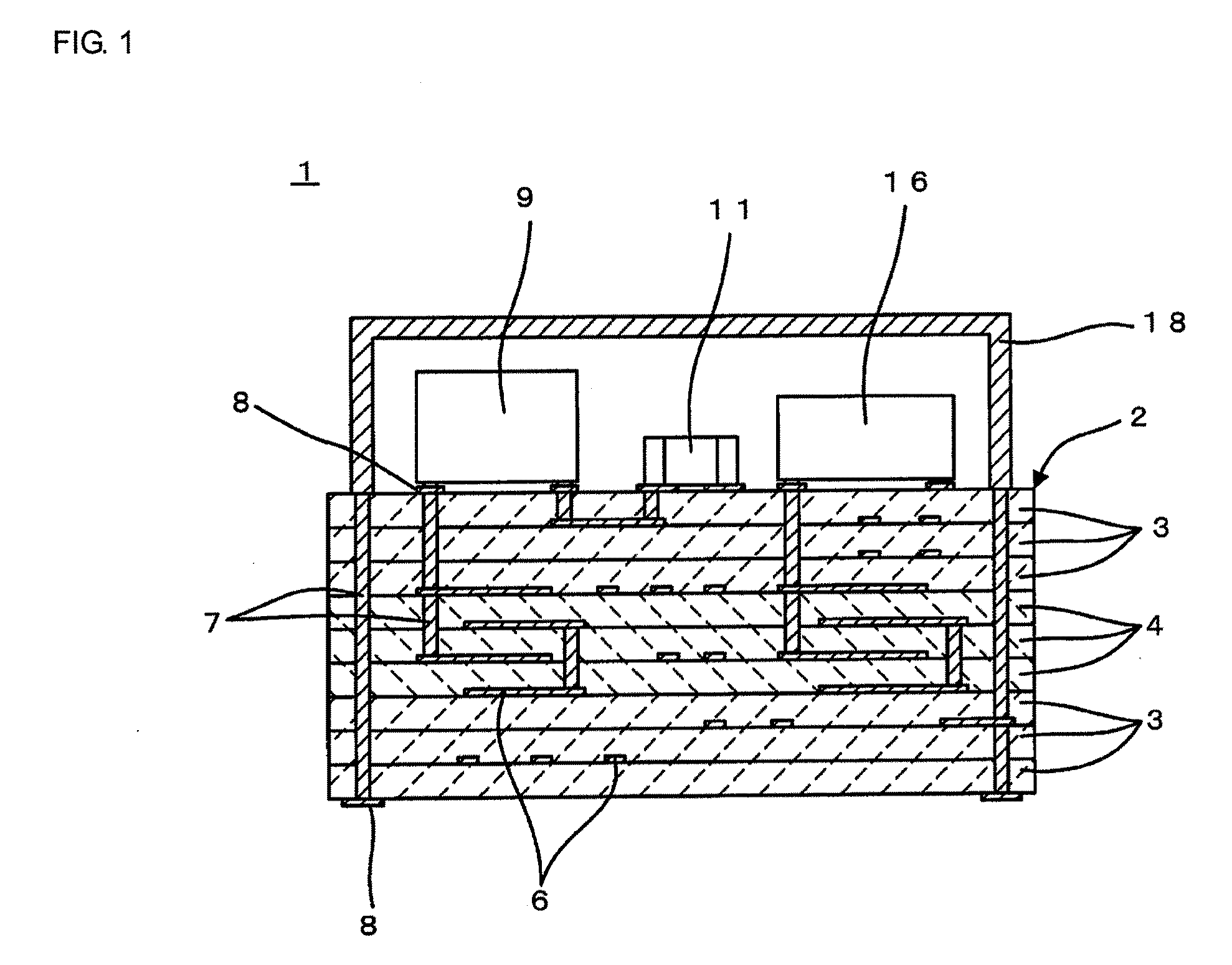
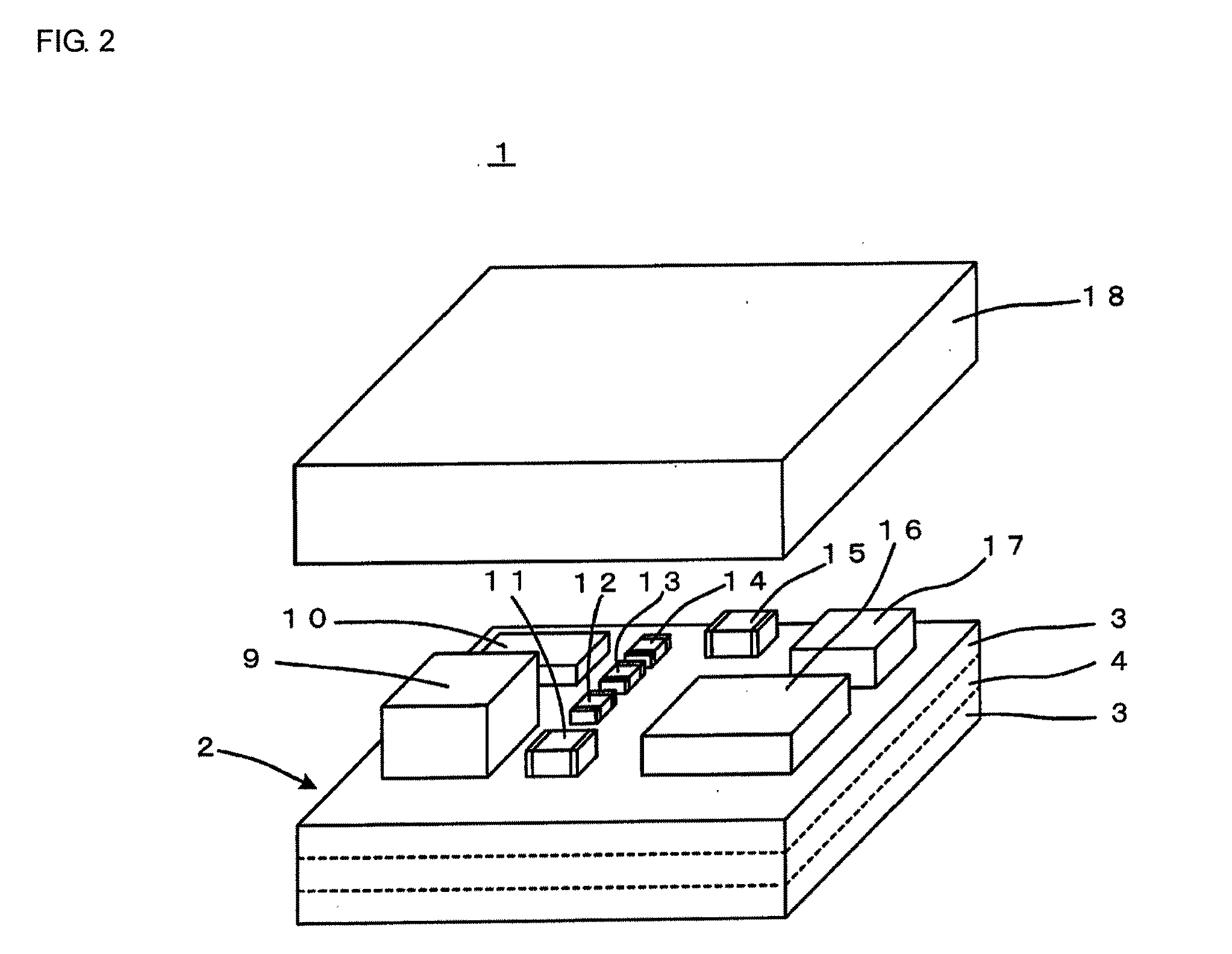
[0176]When the multilayer ceramic substrate 2 of the ceramic multilayer module 1 shown in FIGS. 1 and 2 is manufactured, co-sintering properties between the glass ceramic layers 3 having a low dielectric constant formed by using the glass ceramic composition of the present invention and the high dielectric ceramic layers 4 formed by using a high dielectric ceramic composition become an important issue, and in Experimental Example 3, the co-sintering properties described above were investigated.

[0177]As a high dielectric ceramic composition for high dielectric ceramic layers, Glasses G101, G102, and G103 having compositions shown in Table 6 were prepared. In addition, ceramic powders shown in the column “Ceramic” in Table 7 were prepared.

TABLE 6SiO2B2O3RO [PERCENT BYLi2OZnOGLASS[PERCENT[PERCENTWEIGHT][PERCENT[PERCENTMARKBY WEIGHT]BY WEIGHT]MgOCaOSrOBaOBY WEIGHT]BY WEIGHT]G10125.020.025.010.05.005.010.0G10225.020.025.0015.005.010.0G10325.020.025.005.010.05.010.0

TABLE 7CERAMICGLASSSAMP...


PUM

PropertyMeasurementUnit
molar ratioaaaaaaaaaa
specific surface areaaaaaaaaaaa

Abstract

A glass ceramic composition is provided which can be fired at a temperature of 1,000° C. or less to form a sintered body having a low relative dielectric constant, a small temperature coefficient of resonant frequency, a small change in capacitance before and after a loading test, a high Qf value, high electrical insulating reliability, and a high flexural strength. A glass ceramic composition forming glass ceramic layers laminated to each other in a multilayer ceramic substrate is also provided. The glass ceramic composition includes a first ceramic powder containing forsterite as a primary component; a second ceramic powder containing SrTiO3 and/or TiO2 as a primary component; a third ceramic powder containing BaZrO3 as a primary component; a fourth ceramic powder containing SrZrO3 as a primary component; and a borosilicate glass which contains Li2O, MgO, B2O3, SiO2, and ZnO, and also which contains at least one of CaO, BaO, and SrO.

Description

[0001]This is a continuation of application Serial No. PCT / JP2009 / 054389, filed Mar. 9, 2009, the entire contents of which is incorporated herein by reference.TECHNICAL FIELD[0002]The present invention relates to a glass ceramic composition containing a glass component so as to be fired at a low temperature, a glass ceramic sintered body obtained by firing the glass ceramic composition, and a multilayer ceramic electronic device formed by using this glass ceramic sintered body.BACKGROUND ART[0003]A multifunctional electronic device has been used in electronic apparatus as one effective measure for reducing the size of the apparatus. As the multifunctional electronic device, for example, a ceramic multilayer module may be mentioned.[0004]The ceramic multilayer module has a multilayer ceramic substrate. Wiring conductors are embedded in the multilayer ceramic substrate to serve an electrical connection function and / or to form at least one passive device such as a capacitor and / or an i...

Claims


Application Information

Patent Timeline
Patent Type & Authority Applications(United States)
IPC IPC(8): H01G4/30C03C10/14
CPCC03C3/066H05K3/4629C04B35/20C04B35/462C04B35/486C04B2235/3208C04B2235/3213C04B2235/3215C04B2235/3217C04B2235/3224C04B2235/3227C04B2235/3232C04B2235/3236C04B2235/3248C04B2235/3445C04B2235/365C04B2235/5409C04B2235/5436C04B2235/5445C04B2235/6025C04B2235/96H05K1/0306H05K3/4611C03C12/00H01L2224/16227H01L2924/15192H01L2924/15313H01L2924/16251H01L2924/19105
Inventor ADACHI, HIROSHIGE
Owner MURATA MFG CO LTD
Why Eureka
Try Eureka