
vehicle control device

A vehicle control device, the technology of the vehicle, applied in the direction of the control device, vehicle position/route/altitude control, steering control installed on the vehicle, etc.

Active Publication Date: 2021-12-03
HONDA MOTOR CO LTD
View PDF8 Cites 0 Cited by
  • Summary
  • Abstract
  • Description
  • Claims
  • Application Information

AI Technical Summary

Problems solved by technology

However, there is room for further improvement in fuel consumption in situations where there is no need to specifically set the required driving force of the own vehicle, such as gradually accelerating to the set speed when there are no vehicles around.

Method used


Image

  • vehicle control device
  • vehicle control device
  • vehicle control device

Examples


Embodiment Construction

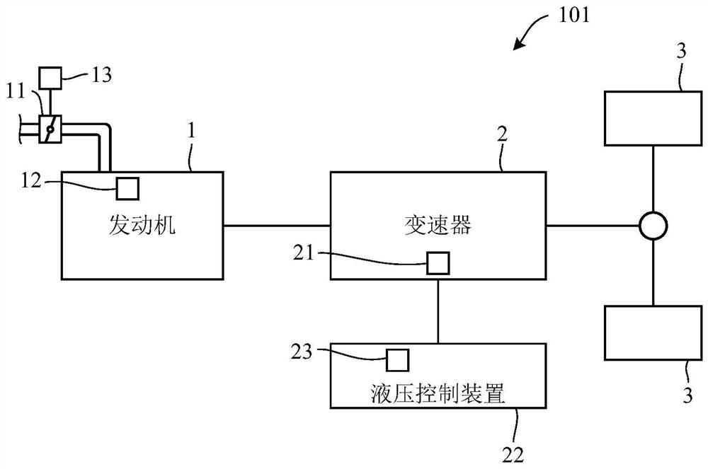
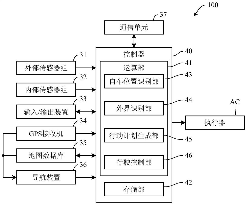
[0021] Below, refer to Figure 1 to Figure 13 Embodiments of the present invention will be described. The vehicle control device according to the embodiment of the present invention is suitable for a vehicle having an automatic driving function (autonomous driving vehicle). figure 1 It is a diagram showing a schematic configuration of a traveling system of an autonomous vehicle (also called "self vehicle" in order to distinguish it from other vehicles) to which the vehicle control device according to the present embodiment is applied. The vehicle 101 can travel not only in an automatic driving mode that does not require a driver's driving operation, but also in a manual driving mode that requires a driver's driving operation.

[0022] Such as figure 1 As shown, a vehicle 101 has an engine 1 and a transmission 2 . The engine 1 is an internal combustion engine (such as a gasoline engine) that mixes intake air supplied through a throttle valve 11 and fuel injected from an inje...


PUM


Abstract

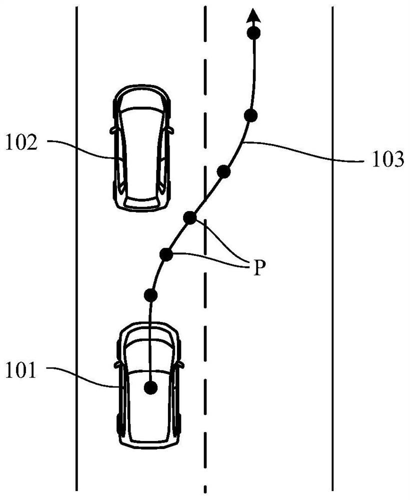
The vehicle control device (100) has: an action plan generation unit (45), which generates an action plan according to the surrounding conditions of the self-driving vehicle (101); and a driving control unit (46), which controls the engine (1) and the transmission (2 ), so that the self-driving vehicle (101) travels in an automatic driving mode according to the generated action plan. An action plan generation unit (45) generates any one of a first action plan including at least position data of an autonomous vehicle (101), and a second action plan including an acceleration command to reach a target speed without including position data. The travel control unit (46) controls the engine (1) and the transmission (2) so that when the second action plan is generated, the target torque is accelerated to reach the target vehicle speed when the fuel consumption per unit travel distance is the least, wherein, The characteristic of the target torque is between the characteristic of the maximum torque corresponding to the engine speed and the characteristic of the torque corresponding to the engine speed to minimize the effective fuel consumption rate of the engine (1).

Description

technical field [0001] The present invention relates to a vehicle control device for controlling a vehicle with an automatic driving function. Background technique [0002] Such a device is conventionally known to generate an action plan including a route to a destination, and to control the gear ratio of the own vehicle based on the action plan so that the own vehicle automatically travels along the route. This device is described in Patent Document 1, for example. The device described in Patent Document 1 is configured so that the automatic driving mode and the manual driving mode can be selected, and different shift diagrams are set for the automatic driving mode and the manual driving mode, so that when the automatic driving mode is selected, the shifting diagram is faster than when the manual driving mode is selected. Upshift on the low speed side. [0003] In the device described in Patent Document 1, the fuel consumption in the automatic driving mode can be improved...

Claims


Application Information

Patent Timeline
Patent Type & Authority Patents(China)
IPC IPC(8): B60W20/00B60W10/06B60W10/11
CPCB60W30/1882B60W40/1005B60W2710/0644B60W2710/0666B60W2710/1005B60W2720/106B60W60/0023B60W2554/80Y02T10/40Y02T10/84B60W10/06B60W10/10B60W10/20B60W30/162B60W30/165B60W2050/0005B60W2520/10B62D1/28B60W2554/801B60W2556/00G05D1/00G05D1/0088
Inventor 岸隆行小西庆明水野俊幸木藤亮
Owner HONDA MOTOR CO LTD
Learn More