Cloth dyeing machine

A cloth dyeing machine and cloth dyeing technology, applied in the field of cloth dyeing machines, can solve the problems of dyeing liquid pollution, low utilization rate of dyeing liquid, uneven dyeing, etc., and achieve the effect of reducing waste and pollution, improving printing and dyeing effect, and fully uniform printing and dyeing

Pending Publication Date: 2019-05-17
FUJIAN HANGGANG TEXTILE TECH CO LTD
View PDF1 Cites 4 Cited by
  • Summary
  • Abstract
  • Description
  • Claims
  • Application Information

AI Technical Summary

Problems solved by technology

[0002] In textile factories, in order to meet the different needs of customers for the color of clothing, it is necessary to dye the cloth. The conventional dyeing method is to soak the cloth in the dye solution for a period of time, but due to the long processing time, it is slowly being used by other dyeing methods. Instead of dyeing methods, most of the current market is divided into two methods: airflow dyeing and overflow dyeing. Airflow dyeing has high requirements for equipment, high operating costs, low dyeing liquor utilization, and high processing costs. The overflow dyeing machine is characterized by its simplicity. It is favored by small processing factories due to its unique structure and low operating costs, but there are still many problems in its use. For example, most of the existing overflow dyeing machines will recycle the excess dye solution during dyeing, but due When dyeing the fabric, the fabric will be accompanied by fibers, which will pollute the dye solution in the dye solution tank and affect the dyeing effect. At the same time, there will be uneven dyeing due to the surface wrinkles of the cloth.
[0003] The patent application number CN201620464268.5 proposes "an overflow dyeing machine for uniform dyeing", which ensures sufficient dyeing by setting multiple dyeing tubes, and fully stretches the cloth under the action of extrusion guide rollers to ensure dyeing Uniform, but the fabric stays in the dyeing tube for a short time, the dye solution sprayed from the dyeing tube can not ensure the all-round dyeing of the cloth, and the simple extrusion roller is easy to cause a large amount of dye solution to stay on the surface of the fabric and the fibers on the surface of the fabric due to tension Adhesion of impurities

Method used


Image

  • Cloth dyeing machine
  • Cloth dyeing machine
  • Cloth dyeing machine

Examples


Embodiment

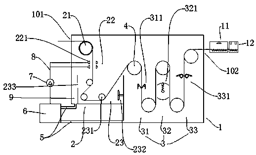
[0034]A cloth dyeing machine, comprising a cloth dyeing box 1, the cloth dyeing box 1 includes a printing and dyeing area 2 provided with a cloth inlet 101 and a functional area 3 provided with a cloth outlet 102, the printing and dyeing area 1 is provided with a The unwinding roller 21 at the entrance 101, the spraying structure 22 located below the unwinding roller 21 and the printing and dyeing tank 23 located below the spraying structure 22, the spraying structure 22 is arranged symmetrically on both sides of the cloth. The spray head 221 on the side, the spray direction of the spray head 221 is perpendicular to the moving direction of the cloth, the printing and dyeing tank 23 is provided with a number of printing and dyeing rollers 231 and agitators 232 that provide tension, one side of the printing and dyeing tank 23 The tank wall is provided with an overflow port 233, and the overflow port 233 is connected to the dyeing liquid recovery pipeline 5 through the overflow ch...


PUM


Abstract

The invention relates to the field of cloth printing and dyeing, in particular to a cloth dyeing machine. The cloth dyeing machine comprises a cloth dyeing box, wherein the cloth dyeing box comprisesa printing and dyeing area with a cloth inlet and a functional area with a cloth outlet; an unwinding roller located at the cloth inlet, a spray structure located below the unwinding roller and a printing and dyeing tank arranged below the spray structure are arranged in the printing and dyeing area; the functional area comprises an extrusion section, a flicking section and a scraping section which are sequentially formed under guide of multiple vertically alternate drive rollers; the printing and dyeing area and the functional area are both connected with a dye tank arranged outside the clothdyeing box through dye recovery pipelines; the dye tank is connected with the spray structure through a power pump and a dye delivery pipeline. The cloth dyeing machine can dye cloth fully and uniformly and scrape extra dye and attached impurities on the surface of cloth.

Description

technical field [0001] The invention relates to the field of cloth printing and dyeing, in particular to a cloth dyeing machine. Background technique [0002] In textile factories, in order to meet the different needs of customers for the color of clothing, it is necessary to dye the cloth. The conventional dyeing method is to soak the cloth in the dye solution for a period of time, but due to the long processing time, it is slowly being used by other dyeing methods. Instead of dyeing methods, most of the current market is divided into two methods: airflow dyeing and overflow dyeing. Airflow dyeing has high requirements for equipment, high operating costs, low dyeing liquor utilization, and high processing costs. The overflow dyeing machine is characterized by its simplicity. It is favored by small processing factories due to its unique structure and low operating costs, but there are still many problems in its use. For example, most of the existing overflow dyeing machines ...

Claims


Application Information

Patent Timeline
Patent Type & Authority Applications(China)
IPC IPC(8): D06B23/18D06B1/02D06B3/18D06B15/08D06B15/00D06B23/20D06G1/00
Inventor 邓作友
Owner FUJIAN HANGGANG TEXTILE TECH CO LTD
Why Eureka
Try Eureka