Concrete pouring process for multi-layer beam slab outer eave structure

A technology for concrete and concrete strength, which is applied in the direction of tools, buildings, and building structures for roof engineering, can solve problems such as concrete sub-strength pouring, and achieve the effect of improving construction progress, ensuring overall stability, and reducing costs.

Inactive Publication Date: 2019-05-17
中兴文建工程集团有限公司
View PDF2 Cites 2 Cited by
  • Summary
  • Abstract
  • Description
  • Claims
  • Application Information

AI Technical Summary

Problems solved by technology

[0003] The purpose of the present invention is to provide a concrete pouring process for the outer eaves structure of multi

Method used


Image

  • Concrete pouring process for multi-layer beam slab outer eave structure

Examples


Embodiment Construction

[0033] The present invention will be described in further detail below in conjunction with the accompanying drawings.

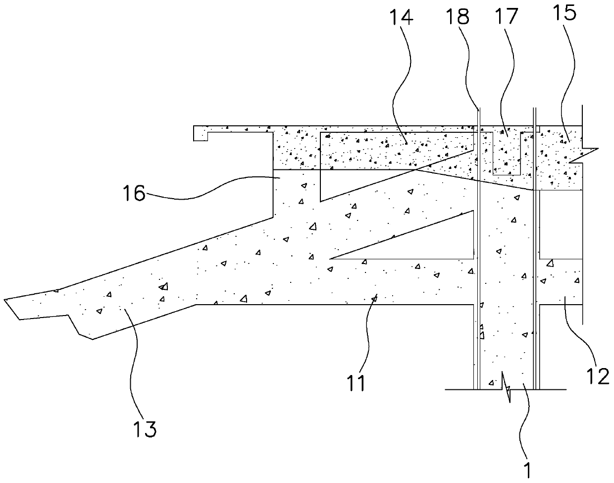
[0034] refer to figure 1 , is a multi-layer girder slab outer eaves structure disclosed by the present invention, comprising a vertical support column 1, on both sides of the support column 1 are respectively fixed horizontally arranged flat joists 11 and flat joist inner beams 12. Wherein the flat joist 11 extends outward.

[0035] refer to figure 1 , a wing angle beam 13 located above the flat joist 11 is fixed on the support column 1 . In this embodiment, the wing angle beam 13 extends obliquely downward on the side facing away from the supporting column 1 , and overlaps the flat joist 11 . Between the wing corner beam 13 and the flat joist beam 11, a connecting beam for connection is provided.

[0036] refer to figure 1 A flat beam 14 and an inner flat beam 15 above the corner beam 13 are fixed horizontally on both sides of the support column 1, wher...


PUM


Abstract

The invention relates to the technical field of construction, in particular to a concrete pouring process for a multi-layer beam slab outer eave structure. The concrete pouring process comprises the following steps: pouring stone-reducing mortar onto the bottom of a supporting column; pouring concrete with a strength grade of C40 into the supporting column; pouring concrete with a strength grade of C40 for a flat support beam from the supporting column; pouring concrete with a strength grade of C40 for the cantilever part of a wing angle beam from the supporting column; pouring concrete with astrength grade of C40 for the wing angle beam from an outerside square column; pouring concrete with a strength grade of C40 for the wing angle beam from the supporting column; pouring concrete witha strength grade of C30 for an inside beam of a flat beam from the supporting column; pouring concrete with a strength grade of C30 for the flat beam and a horizontal cross beam from the supporting column. Through providing the concrete pouring process for the multi-layer beam slab outer eave structure, the problem of concrete pouring by strength in the presence of the cantilever beam is effectively solved.

Description

technical field [0001] The invention relates to the technical field of building construction, in particular to a concrete pouring process for a multi-layer beam-slab outer eaves structure. Background technique [0002] Many buildings now adopt the architectural form combining modern technology and ancient architectural art style, thus forming a beam-slab structure that replaces the ancient wooden structure with cast-in-place reinforced concrete. In order to achieve the use effect and safety requirements, three or more layers of beams are often arranged to intersect, and most of the beams are cantilevered structures. According to the design and specification requirements, it is generally required that the concrete strength of the column is stronger than that of the beam by a higher grade. However, it is very difficult to pour layers separately in the construction of this kind of multi-layer beam-slab structure of the antique building, and when there are cantilever beams In t...

Claims


Application Information

Patent Timeline
IPC IPC(8): E04D13/158E04D15/07
Inventor 胡江龙
Owner 中兴文建工程集团有限公司
Why Eureka
Try Eureka