Buffer protection transmission device and method for shuttle type distribution trolley

A cloth trolley and transmission technology, applied in vibration suppression adjustment, lighting and heating equipment, furnace types, etc., can solve the problems of uncontrollable adjustment of buffer stroke, influence of device operation, etc., to improve rigid force conditions and reduce friction. , reduce the effect of inertial impact

Active Publication Date: 2019-05-17
GAOYOU INST CO LTD DALIAN UNIV OF TECH
View PDF15 Cites 5 Cited by
  • Summary
  • Abstract
  • Description
  • Claims
  • Application Information

AI Technical Summary

Problems solved by technology

[0006] The object of the present invention is to provide a buffer protection transmission device and method for a shuttle-type cloth trolley, so as to solve the problem that the elastic transition connection device arranged between the wheel and the axle cannot control and adjust the buffer stroke when the above device is used, the buffer stroke is too long or Too short will have a negative impact on the operation of the device

Method used


Image

  • Buffer protection transmission device and method for shuttle type distribution trolley
  • Buffer protection transmission device and method for shuttle type distribution trolley
  • Buffer protection transmission device and method for shuttle type distribution trolley

Examples


Embodiment 1

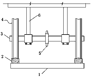
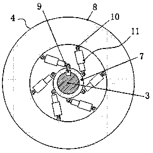
[0033] See Figure 1-3 , The present invention provides a technical solution: a buffer protection transmission device for a shuttle-type distributing trolley, comprising a trolley base 1, a moving track 2, a transmission wheel shaft 3, a roller assembly 4, a transmission sprocket 5 and a trolley frame 6. The moving track 2 is laid symmetrically on the top of the trolley base 1. The roller assembly 4 is arranged at both ends of the drive axle 3. The roller assembly 4 moves along the moving track 2, and the drive sprocket 5 is fixedly sleeved on the middle of the drive axle 3 by a key connection. , The trolley frame 6 is movably installed on the drive axle 3; the roller assembly 4 includes a mounting inner ring 7 and a movable outer ring 8. The inner ring of the mounting inner ring 7 is sleeved with the drive axle 3 and is fixed and driven by the key 9. A buffer device 11 is hinged between the outer part of the ring 7 and the inner wall of the movable outer ring 8 through a hinge...

Embodiment 2

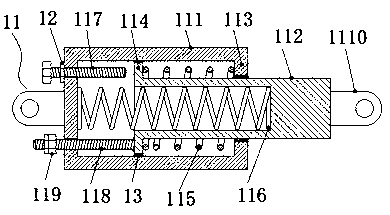
[0038] The embodiment of the present invention provides a buffer protection transmission device for a shuttle-type distributing trolley. On the basis of Embodiment 1, a tightening thin nut 12 is screwed on the constriction screw 117 to play a role of tightening and preventing loosening.

Embodiment 3

[0040] The embodiment of the present invention provides a buffer protection transmission device for a shuttle-type distributing trolley. On the basis of embodiment 1, between the inner edge 113 and the outer wall of the inner sleeve 112 and before the outer flange 114 and the inner wall of the outer sleeve 111 Both are provided with a lubricating seal ring 13, which reduces the resistance of the components and improves the cushioning effect.


PUM


Abstract

The invention discloses a buffer protection transmission device and method for a shuttle type distribution trolley in the technical field of metallurgical mechanical equipment. The device comprises atrolley base, moving rails, a transmission axle, roller assemblies, a transmission chain wheel and a trolley frame; the moving rails are paved on the top of the trolley base in a left and right symmetry manner, the roller assemblies are arranged at the two ends of the transmission axle, the roller assemblies move along the moving rails, the transmission chain wheel is fixedly arranged at the middle portion of the transmission axle in a key connection manner, and the trolley frame is movably mounted on the transmission axle; and each roller assembly comprises an installing inner ring and a moving outer ring, wherein the inner circle of the installing inner ring and the transmission axle are connected in a sleeving manner and are in key fixing transmission, and a buffer device is hinged between the outer part of the installing inner ring and the inner wall of the moving outer ring through a hinge base; and each buffer device comprises an outer sleeve and an inner sleeve. By means of thebuffer protection transmission device and method for the shuttle type distribution trolley, the buffer stroke can be adjusted to achieve the optimum compromise effect.

Description

Technical field [0001] The invention relates to the technical field of metallurgical machinery and equipment, in particular to a buffer protection transmission device and method for a shuttle-type distributing trolley. Background technique [0002] The shuttle cloth machine is suitable for the feeding operation of the sintering process. The sintered materials are mixed on the conveyor belt of the shuttle cloth machine and fall into the trough through the conveyor belt. Because the shuttle cloth machine has wheels, it can reciprocate, so that the material surface falling into the trough and the particle size of the material in the trough tend to be uniform, which is beneficial to the air permeability and burning through of the sinter. [0003] However, most of the wheels of the existing shuttle cloth machine are rigid wheels, that is, the wheel and the axle are connected by keys or bearings, and a sprocket is arranged in the middle of the axle. The motor drives the sprocket chain an...

Claims


Application Information

Patent Timeline
IPC IPC(8): F16F15/123F16F1/02F27B21/10F27D3/12
Inventor 李斌李昕欣
Owner GAOYOU INST CO LTD DALIAN UNIV OF TECH
Why Eureka
Try Eureka