Fluid distribution valve and fluid treatment device

A fluid distribution valve and fluid channel technology, applied in valve devices, ion exchange processing devices, feeding devices, etc., can solve the problems of high operating cost, high manufacturing difficulty, large inertial force, etc., to simplify equipment structure and reduce manufacturing. The effect of difficulty and equipment cost

Pending Publication Date: 2019-05-17
XIAMEN FILTER & MEMBRANE TECH
View PDF1 Cites 3 Cited by
  • Summary
  • Abstract
  • Description
  • Claims
  • Application Information

AI Technical Summary

Problems solved by technology

[0003] The above-mentioned continuous fluid processing device places the reaction vessel on the turntable, and achieves the purpose of continuous fluid feeding through the indexing movement of the rotatable valve part and the reaction vessel. However, it is well known that in the case of larger equipment, the inertial force is very large , requires a very large kinetic energy to achieve accurate transmission, which means that the manufacturing of the equipment is difficult, the investment is large, and the operating cost is also high, which greatly limits the scope of use of the continuous fluid processing device

Method used


Image

  • Fluid distribution valve and fluid treatment device
  • Fluid distribution valve and fluid treatment device
  • Fluid distribution valve and fluid treatment device

Examples


Embodiment 1

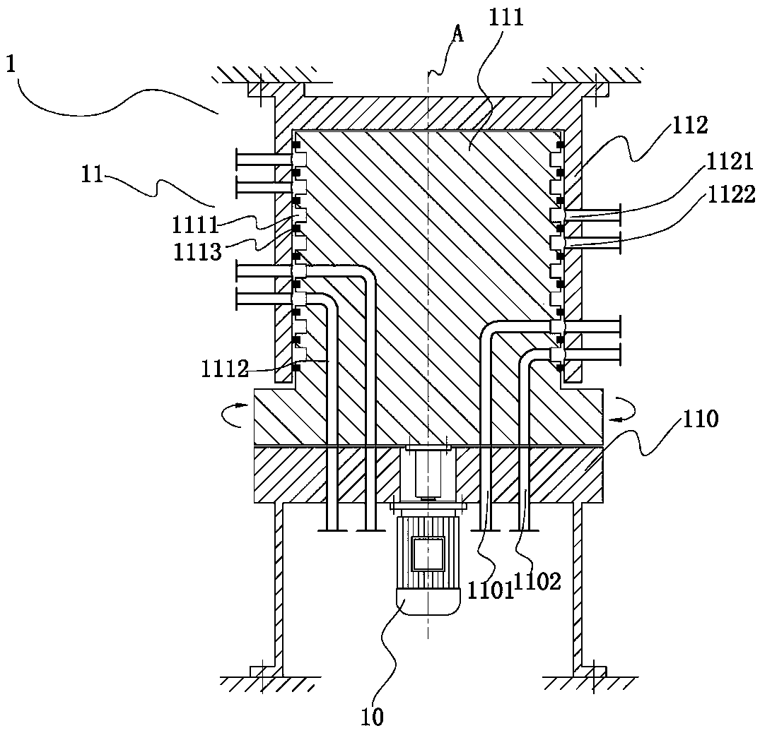
[0021] Such as figure 1 As shown, the fluid dispensing valve 1 of the present invention includes a valve assembly 11 and a transmission device 10;

[0022] Wherein the valve assembly includes a fixed valve disc 110, a rotating valve core 111 and a fixed sleeve 112;

[0023] On the fixed valve disc 110, there are N pairs (N≥2) correspondingly arranged and penetrating the body of the fixed valve disc. Each pair of fluid channels includes a feed fluid channel 1101 and a discharge fluid channel 1102;

[0024] The rotating valve core 111 is arranged on the upper part of the fixed valve disc 110, and is sealedly connected with the fixed sleeve 112 in the fixed sleeve 112 and can rotate around the central axis A; the fixed sleeve 112 is provided with M pairs of feed ports 1121 and outlets. The feed port 1122; the rotary valve core 111 is provided with M pairs of annular flow channels 1111, and the annular flow channels 1111 correspond to and communicate with the feed port 1121 and ...

Embodiment 2

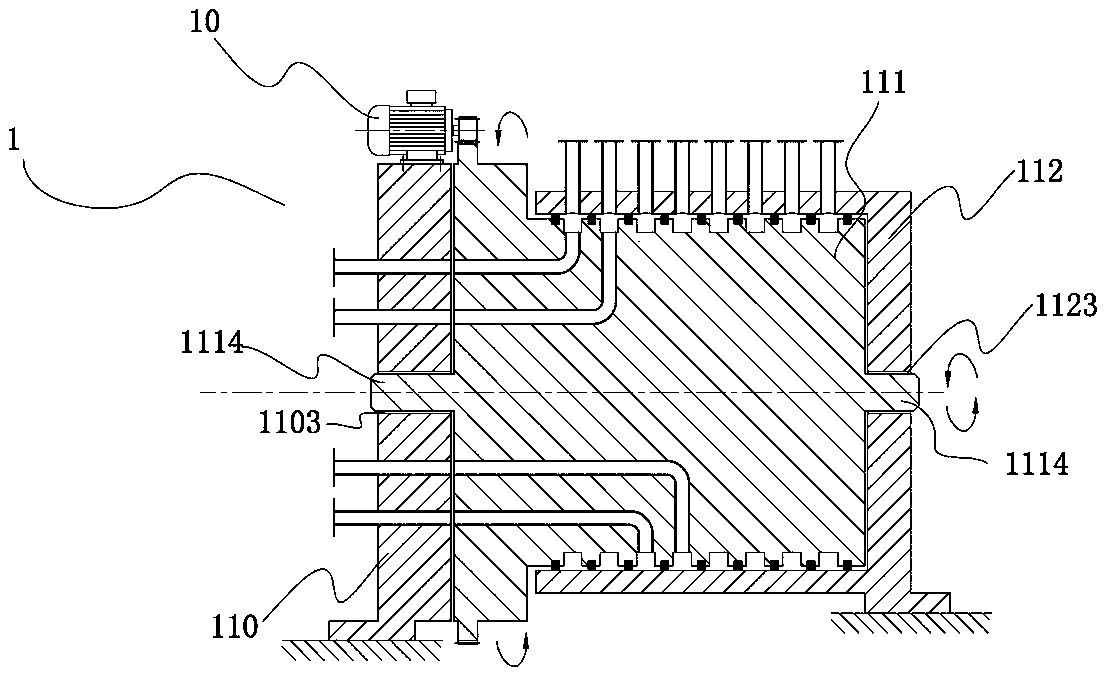
[0026] Such as figure 2 As shown, the difference between it and Embodiment 1 is that the entire fluid distributing valve is arranged horizontally, which is suitable for occasions with a large number of annular flow passages, feed inlets, and discharge outlets (such as vertical, rotary valve cores) will need to be set particularly high), which greatly reduces the height of the equipment. The transmission device 10 is set on the side of the rotary valve core 111 and connected with the rotary valve core 111. The connection method can be conventional chain connection, gear connection, etc., driven by the side The rotary spool 111 rotates. Further, as a preferred mode, recessed parts 1103 and 1123 are provided at the center of the side walls of the fixed valve disc 110 and the fixed sleeve 112, and convex parts 1114 are provided at both ends of the rotary valve core 111, and the convex parts 1114 are arranged in the recessed parts. It is movably connected with the concave part. I...

Embodiment 3

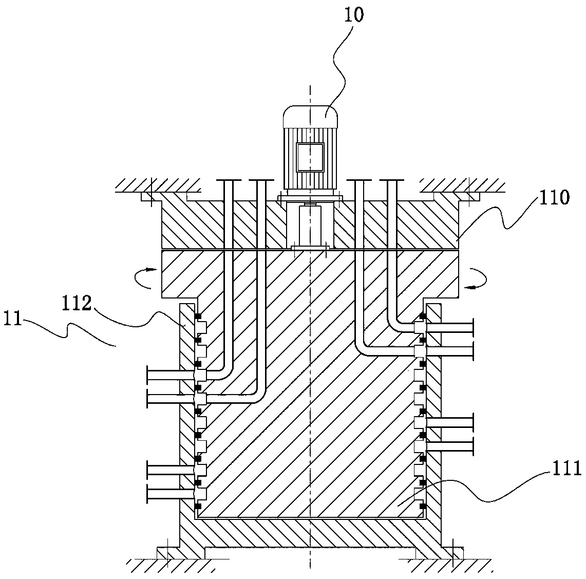
[0028] Such as image 3 As shown, the difference between it and Embodiment 1 is that the rotary valve core 111 is located at the lower part of the fixed valve disc 110, and the purpose of the invention can also be achieved in this way.

[0029] The present invention also includes a fluid treatment device using the above-mentioned fluid dispensing valve, such as Figure 4 As shown, the fluid distribution treatment device of the present invention includes a fluid distribution valve 1 and N reaction vessels 2, and the reaction vessel 2 is provided with a feed liquid inlet 21 and a feed liquid outlet 22, and each pair of fixed valve discs 101 The feed fluid channel 1101 communicates with the feed liquid inlet 21 of the corresponding reaction vessel 2 through a pipeline, and the discharge fluid channel 1102 communicates with the feed liquid outlet 22 of the corresponding reaction vessel 2 through a pipeline.

[0030] In specific use, taking the fluid treatment device applied to ion...


PUM


Abstract

The invention discloses a fluid distribution valve. The fluid distribution valve comprises a valve assembly and a transmission device. The fluid distribution valve is characterized in that the valve assembly comprises a fixed valve disc, a rotary valve element and a fixed sleeve, N pairs of fluid channels penetrating through a valve disc body are uniformly distributed on the fixed valve disc, eachpair of fluid channels comprises one feeding fluid channel and one discharging fluid channel, the rotary valve element is arranged at the upper part, the lower part or the side part of the fixed valve disc and arranged in the fixed sleeve, is in sealing connection with the fixed sleeve and can rotate around the central axis, and the transmission device is connected with the rotary valve element and drives the rotary valve element to rotate. The invention further provides a fluid treatment device adopting the fluid distribution valve. According to the fluid distribution valve and the fluid treatment device adopting the fluid distribution valve, the complex "whirligig structure" is avoided, meanwhile, the equipment structure is simplified, the manufacturing difficulty and the equipment costof equipment are greatly reduced, moreover, the whole equipment can stand and lie down, and then the requirements of various application occasions can be met.

Description

technical field [0001] The invention relates to the field of fluid treatment, in particular to a fluid distribution valve and a fluid treatment device. Background technique [0002] The basic structure of the existing continuous fluid processing device is shown in the Chinese invention patent "A device for chemical or physical processing" with the publication number CN 1849167A. its like Figure 4 As shown, it mainly includes: a fixed frame with a turntable, the turntable is arranged on the frame so that it can rotate around the central axis, there are a plurality of reaction vessels on the turntable, a valve assembly is provided, and the valve assembly includes a disc-shaped rotatable valve member disposed concentrically with respect to said central axis and a fixed valve member disposed opposite the rotatable valve member and connected to the frame, each valve member having an orifice, said The orifices are moved relative to each other in a varying sequence, connections a...

Claims


Application Information

Patent Timeline
Patent Type & Authority Applications(China)
IPC IPC(8): F16K11/085F16K27/06B01J4/00B01J47/00
Inventor 虞美辉葛尚勇范仁锋彭广生湛科
Owner XIAMEN FILTER & MEMBRANE TECH
Why Eureka
Try Eureka