Electronic product sintering and shaping rotating shaft

A technology for electronic products and rotating shafts, which is applied in the field of sintering and shaping rotating shafts of electronic products, can solve the problems of prolonged processing time, insufficient sintering, and increased energy consumption, so as to reduce time and energy consumption, avoid insufficient sintering, and save costs. Effect

Inactive Publication Date: 2019-05-17
天津七垚电子科技有限公司
View PDF0 Cites 2 Cited by
  • Summary
  • Abstract
  • Description
  • Claims
  • Application Information

AI Technical Summary

Problems solved by technology

[0002] The sintering and shaping of electronic products generally use electronic component sintering furnaces. Electronic products such as ferrite, ceramic inductor substrates, ceramic capacitor dielectric substrates, lithium iron phosphate powder and powders for various electronic products, etc., carry blanks The material receiving plate of the piece is sent to the transition platform between the input conveying device and the output conveying device by the input conveying device, and then the material receiving plate is pushed to the output conveying device by the pushing mechanism arranged at the transition platform, and is conveyed by the output The device transports the loading plate to the furnace mouth of the furnace body, and then pushes it into the furnace by the pushing mechanism at the output conveying device. During the sintering process, there are the following problems: since the sintering furnace is placed The blank on the carrier plate is heated to make the top and surrounding of the blank sinter better, but the bottom surface will be insufficiently sintered due to uneven heating. In order to make the blank sinter evenly, the sintering time is often extended or carried out Secondary sintering, which on the one hand prolongs the processing time, on the other hand increases energy consumption and increases the cost

Method used


Image

  • Electronic product sintering and shaping rotating shaft
  • Electronic product sintering and shaping rotating shaft

Examples


Embodiment Construction

[0016] The following will clearly and completely describe the technical solutions in the embodiments of the present invention with reference to the accompanying drawings in the embodiments of the present invention. Obviously, the described embodiments are only some, not all, embodiments of the present invention.

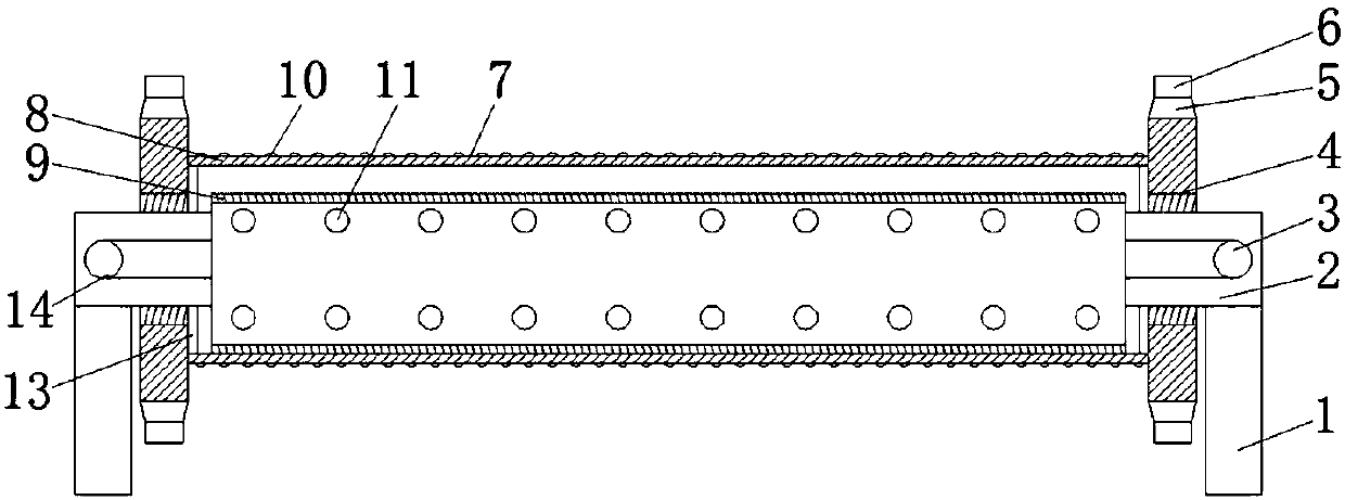
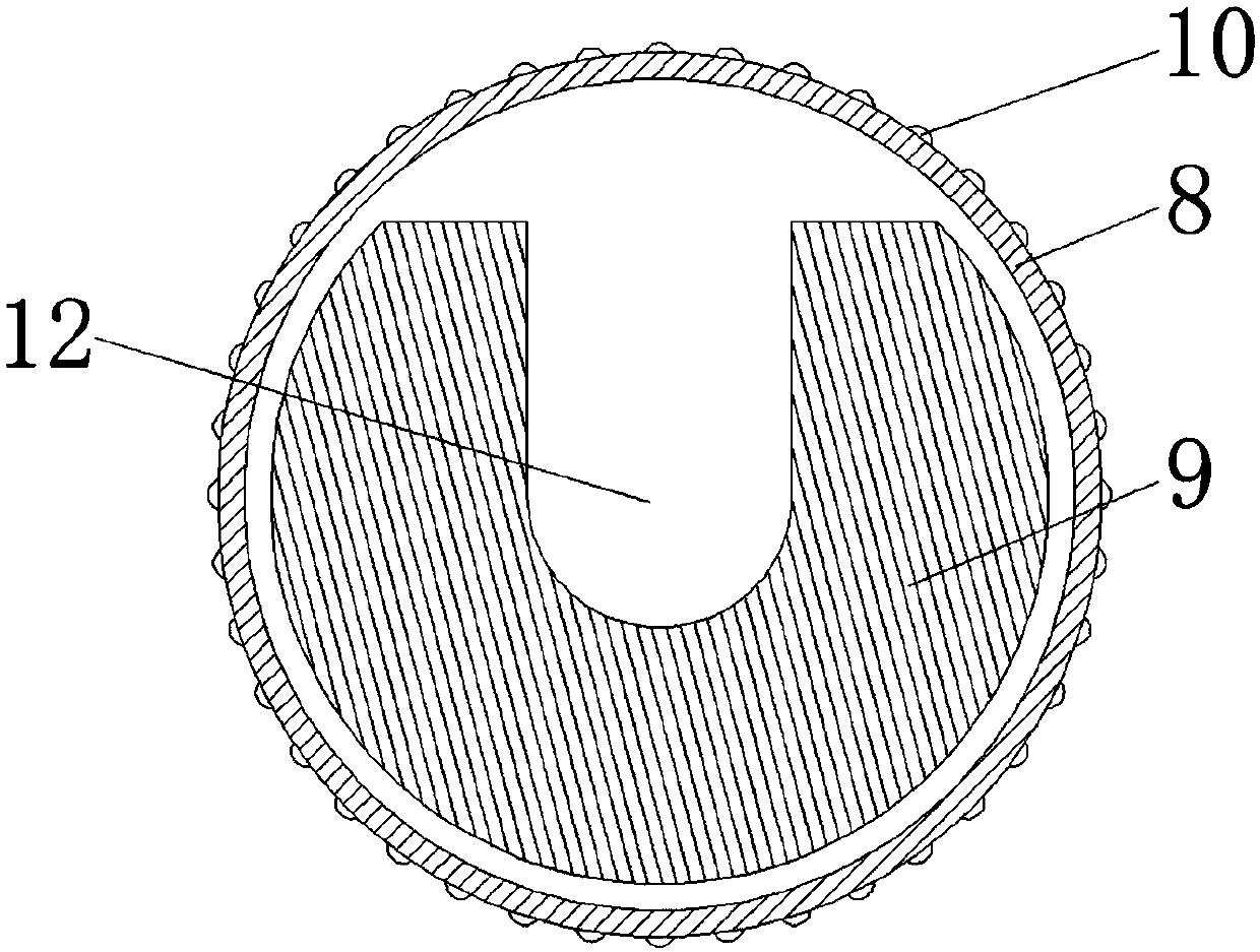
[0017] refer to Figure 1-2 , a sintered and shaped rotating shaft for electronic products, including a base 1 and a shaft body 7, a support rod 2 is welded horizontally on the top of the base 1, one end of the support rod 2 is fixed to the inner ring of the bearing 4 through a key pin, and the number of the shaft body 7 is Multiple, and the shaft body 7 includes an outer shaft 8 and an inner shaft 9, one end of the support rod 2 is welded and fixed to one end of the inner shaft 9, the outer ring of the bearing 4 is welded and fixed to one end of the outer shaft 8, and the outer ring of the bearing 4 The key pin is fixed with the gear 5, and each gear 5 is connected ...


PUM


Abstract

The invention discloses an electronic product sintering and shaping rotating shaft. The rotating shaft comprises a base and shaft bodies, wherein a supporting rod is welded to the top end of the base,one end of the supporting rod is fixed to the inner ring of a bearing, one end of the supporting rod is fixed to one ends of inner shafts, the outer ring of the bearing is fixed to one ends of outershafts, and the outer side of the outer ring of the bearing is fixed to gears; and every two gears are connected through a chain, heating pipelines are inserted into first through holes of the supporting rod, a U-shaped opening is vertically and upwards formed in each inner shaft, outlets of the heating pipelines are erected on the bottom surfaces of the U-shaped openings, a second through hole isobliquely formed in the surface of each outer shaft, and a protruding block is arranged on the surface of each outer shaft. According to the rotating shaft, the second through holes are obliquely formed in the surfaces of the outer shafts, and when the shaft bodes rotate, high-temperature gas is blown to the bottom end of a blank through the second through holes, so that the surface of the blankis uniformly heated and sintered.

Description

technical field [0001] The invention relates to the technical field of sintering of electronic products, in particular to a sintering and shaping rotating shaft of electronic products. Background technique [0002] The sintering and shaping of electronic products generally use electronic component sintering furnaces. Electronic products such as ferrite, ceramic inductor substrates, ceramic capacitor dielectric substrates, lithium iron phosphate powder and powders for various electronic products, etc., carry blanks The material receiving plate of the piece is sent to the transition platform between the input conveying device and the output conveying device by the input conveying device, and then the material receiving plate is pushed to the output conveying device by the pushing mechanism arranged at the transition platform, and is conveyed by the output The device transports the loading plate to the furnace mouth of the furnace body, and then pushes it into the furnace by th...

Claims


Application Information

Patent Timeline
Patent Type & Authority Applications(China)
IPC IPC(8): F27B17/00F27D1/00
Inventor 赵亮
Owner 天津七垚电子科技有限公司
Why Eureka
Try Eureka