Portable fuze booster tube decomposing machine

A technology of detonator and decomposition machine, which is applied to weapon accessories, ammunition, offensive equipment, etc. It can solve the problems of backward mechanical structure and electrical control system, failure to take fuze detonator accident protection into consideration, and inability to disassemble the fuze detonator. , to achieve the effect of simple and efficient decomposition work, easy maintenance and repair, and enhanced safety protection

Active Publication Date: 2019-05-17
中国人民解放军68128部队
View PDF5 Cites 0 Cited by
  • Summary
  • Abstract
  • Description
  • Claims
  • Application Information

AI Technical Summary

Problems solved by technology

[0003] In the prior art, when the fuze detonator is disassembled, it needs to be carried out in a special repair shop or a fuze component testing center, and special equipment is required. The special equipment for disassembling the fuze detonator in the prior art is complex in structure, bulky, heavy, and poor in mobility , making it impossible for troops to disassemble the fuze detonator during field training and stationing in remote areas
[0004] The mechanical structure and electrical control system of the fuze detonator decomposition equipment in the prior art are backward, with high failure rate, poor work quality and low production efficiency
[0005] Most of the fuze booster decomposition equipment in the prior art does not consider the accident protection when the fuze booster is disassembled. Once an accident occurs when the fuze booster is disassembled, it does not have safety protection capabilities

Method used


Image

  • Portable fuze booster tube decomposing machine
  • Portable fuze booster tube decomposing machine
  • Portable fuze booster tube decomposing machine

Examples


Embodiment Construction

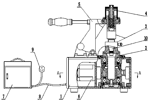
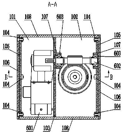
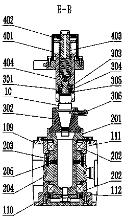
[0053] like figure 1 As shown, a portable fuze detonator decomposition machine of the present invention includes a box body 1, a transmission assembly 2, a fuze element decomposition assembly 3, a pressing device 4, a rotary device 5, a power device 6, a control box 7, a control Cable 8, power cord 9 and fuze element 10. another example figure 2 , image 3 As shown, the box body 1 is a square box body, the box body is provided with an upper panel 109 and a lower panel 110, two left and right panels 106 and two front and rear panels 108 are arranged between the upper panel 109 and the lower panel 110, each left and right panel 106 inboards are also provided with left and right inner baffles 105, and the upper side of the upper panel 109 and the upper side of the lower panel 110 are also welded with mounting blocks 104, and the left and right inner baffles 105 and the left and right panels 106 are installed on the mounting blocks 104 by bolts. The bottom of the box body 1 is...


PUM


Abstract

The invention relates to a fuze booster tube decomposing device, in particular to a portable fuze booster tube decomposing machine. The portable fuze booster tube decomposing machine has the small volume, strong portability, high efficiency and light weight, and can be fitted with field troops; according to the portable fuze booster tube decomposing machine, manners of spring compression and physical worm transmission are used, motors are used for providing power, decomposition work is simple and efficient, the decomposition work can be completed depending on manpower in the absence of electric power, operation is easy and convenient, practicability is high, and the limitation of the power environment is avoided; as for different fuze elements, different fuze element decomposing assembliescan be quickly replaced, the applicability is high, and booster tube decomposing operation work of series fuzes including the mechanical fuze, the time fuze, the piezoelectric fuze, the radio fuze and the proximity fuze can be completed; and the portable fuze booster tube decomposing machine is compact in design, low in cost, simple in operation, practical, reliable and easy to maintain and repair. The portable fuze booster tube decomposing machine adopts a box body in the explosion-proof design, a control box and the box body are separately designed, the safety protection setting is furtherstrengthened, and the safety protection work of an operator is greatly strengthened.

Description

technical field [0001] The invention relates to a decomposing device for a fuze detonator, in particular to a portable detonator for a fuze detonator. Background technique [0002] Ammunition is a kind of military equipment and material that directly kills, damages or destroys enemy fortifications and armored targets in modern warfare. When monitoring ammunition quality, it is necessary to use The ammunition's fuze booster is disassembled. [0003] In the prior art, when the fuze detonator is disassembled, it needs to be carried out in a special repair shop or a fuze component testing center, and special equipment is required. The special equipment for disassembling the fuze detonator in the prior art is complex in structure, bulky, heavy, and poor in mobility , so that the troops cannot disassemble the fuze detonator during field training and stationing in remote areas. [0004] The mechanical structure and electric control system of the decomposing equipment of the fuze ...

Claims


Application Information

Patent Timeline
Patent Type & Authority Applications(China)
IPC IPC(8): F42B33/06
Inventor 王斌陈青蒲亮韩路阳牛星瞳
Owner 中国人民解放军68128部队
Why Eureka
Try Eureka