
Fixing device and heating production line

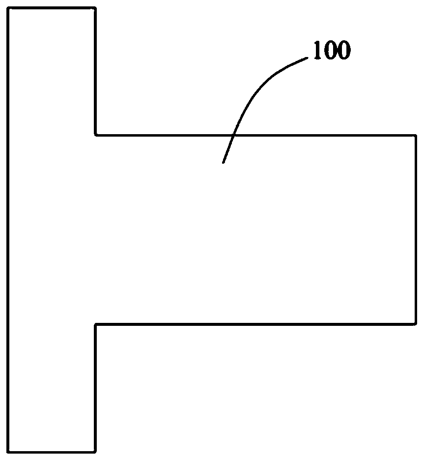
A technology of fixing device and production line, applied in induction heating, induction heating device, fiber mechanical structure, etc., can solve the problems of operator burns, glass tube 100 position deviation, easy water seepage of finished products, etc., to ensure the tight fit effect. , The heating uniformity is good, and the effect of increasing the reuse rate

Inactive Publication Date: 2019-05-17
GUANGDONG HENGTONG PHOTOELECTRIC SCI & TECH
View PDF11 Cites 3 Cited by
  • Summary
  • Abstract
  • Description
  • Claims
  • Application Information

AI Technical Summary

Problems solved by technology

[0004] First of all, in the actual production process, the steel wire cannot be guaranteed to be always in the middle of the glass tube 100, the heating effect of the steel wire is not good, and the heating uniformity is not good, which will cause a gap between the steel wire and the cushion of the steel wire reinforcement, which cannot be carried out. The tight fit makes the finished product prone to water seepage and the quality of optical cable products is not good
At the same time, the steel wire is easy to scratch the inner wall of the glass tube 100, which affects the service life of the glass tube 100
[0005] Secondly, the user needs to manually wind the induction coil onto the glass tube 100 when using it. Since the surface of the glass tube 100 is relatively smooth, the operation is relatively difficult, and the position of the induction coil relative to the glass tube 100 is prone to shift or fall off.
[0006] Thirdly, the existing high-frequency heaters cannot measure the temperature of the steel wire, and the power parameters of the high-frequency heater can only be roughly set by touching the surface of the steel wire. There is a danger of the operator being burned, and the process quality cannot be guaranteed

Method used


Image

  • Fixing device and heating production line
  • Fixing device and heating production line
  • Fixing device and heating production line

Examples


Embodiment Construction

[0044] In order to make the technical problems solved by the present invention, the technical solutions adopted and the technical effects achieved clearer, the technical solutions of the embodiments of the present invention will be further described in detail below in conjunction with the accompanying drawings. Obviously, the described embodiments are only the technical solutions of the present invention. Some, but not all, embodiments. Based on the embodiments of the present invention, all other embodiments obtained by those skilled in the art without creative efforts fall within the protection scope of the present invention.

[0045] In the description of the present invention, unless otherwise clearly specified and limited, the terms "connected", "connected" and "fixed" should be understood in a broad sense, for example, it can be a fixed connection, a detachable connection, or an integrated ; It can be a mechanical connection or an electrical connection; it can be a direct...


PUM


Abstract

The invention belongs to the technical field of optical cable production and manufacture, and discloses a fixing device and a heating production line. The fixing device comprises a glass tube, a sleeve and two fixing mechanisms, wherein the sleeve is coaxially sheathed to one end of the glass tube; the sleeve and the glass tube are used for a workpiece to be penetrated, and the two fixing mechanisms are symmetrically positioned on two sides of the sleeve and can penetrate through the sleeve; and the positions, which are relative to the sleeve, of the two fixing mechanisms are adjustable to jointly clamp the workpiece, and the glass tube, the sleeve and the workpiece are coaxial. The positions, which are relative to the sleeve, of the two fixing mechanisms are regulated to enable the two fixing mechanisms to be independently abutted against two sides of the workpiece, so that the central axial line of the workpiece, the central axial line of the sleeve and the central axial line of theglass tube are positioned on the same line, and the workpiece guarantees to be positioned on the middle position of the glass tube. By use of the fixing device, heating evenness is good, a heating effect is guaranteed, a gap between a steel wire and a protection steel wire reinforcement element cushion layer is reduced, a tight lamination effect between the steel wire and the protection steel wirereinforcement element cushion layer is guaranteed, and a situation of the water seepage of a produced finished product is reduced so as to improve cost quality.

Description

technical field [0001] The invention relates to the technical field of optical cable production and manufacturing, in particular to a fixing device and a heating production line. Background technique [0002] During the manufacturing process of the optical cable, the steel wire in the optical cable needs to be heated together by a high-frequency heater and its matching quartz glass tube, and then a layer of protective steel wire reinforcement cushion needs to be coated on the outside of the heated steel wire for protection. role. [0003] Such as figure 1 As shown, the structure of the glass tube 100 is simple, which is a tubular structure, and the openings at both ends are used for the penetration of steel wires, which play a role in positioning. The induction coil of the high-frequency heater is wound on the glass tube 100, so that the high-frequency heater passes through the Heating induction coil realizes heating of steel wire. There is following defective in prior ar...

Claims


Application Information

Patent Timeline
IPC IPC(8): G02B6/44H05B6/10
Inventor 林佳敏张水先李小军曾辉胡珍林丽华张发杰
Owner GUANGDONG HENGTONG PHOTOELECTRIC SCI & TECH
Features
  • Generate Ideas
  • Intellectual Property
  • Life Sciences
  • Materials
  • Tech Scout
  • Unparalleled Data Quality
  • Higher Quality Content
  • 60% Fewer Hallucinations
Learn More