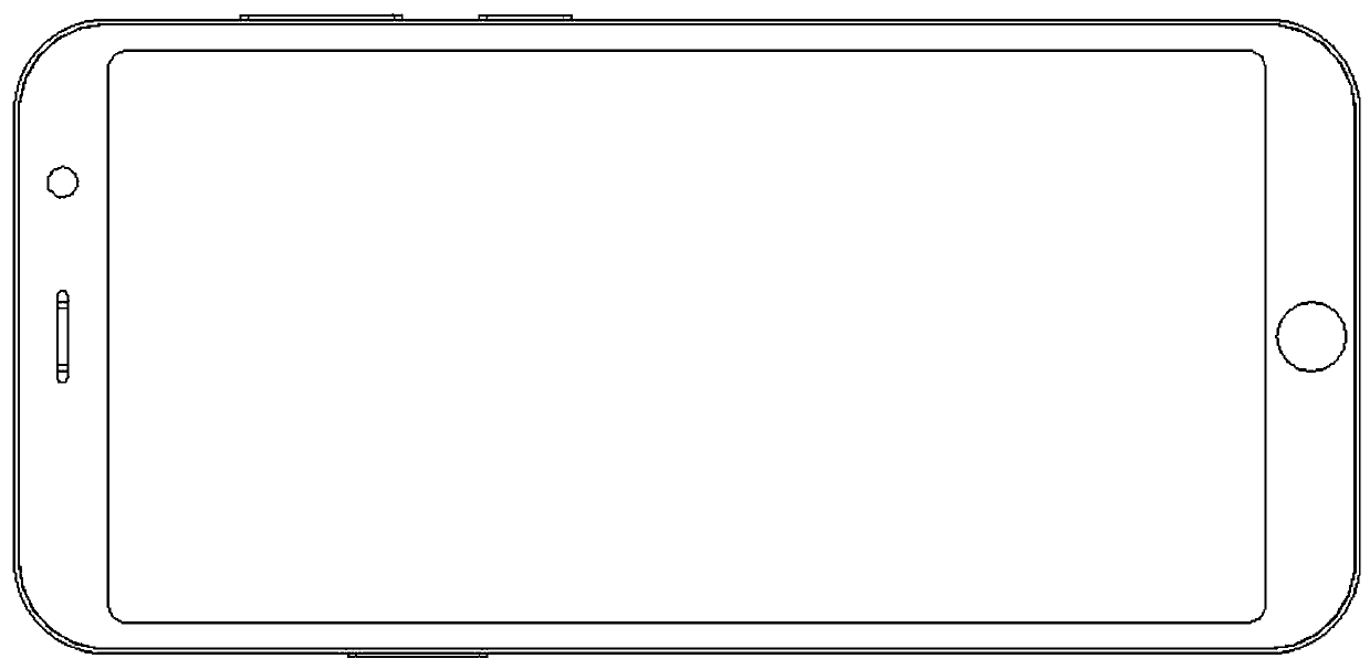
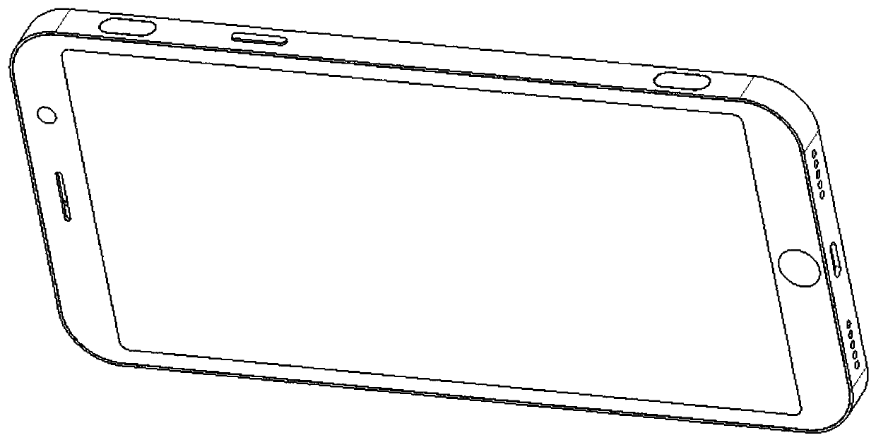
Housing assembly and intelligent terminal with the housing assembly
A technology for housing components and smart terminals, which is applied to the structure of telephones, etc., can solve the problems of short strokes that cannot meet 100% user needs, and cannot obtain physical button strokes and feedback feel, etc., so as to improve user experience and maintain integration. The effect of simple and flexible structure
- Summary
- Abstract
- Description
- Claims
- Application Information
AI Technical Summary
Problems solved by technology
Method used
Image
Examples
Embodiment 1
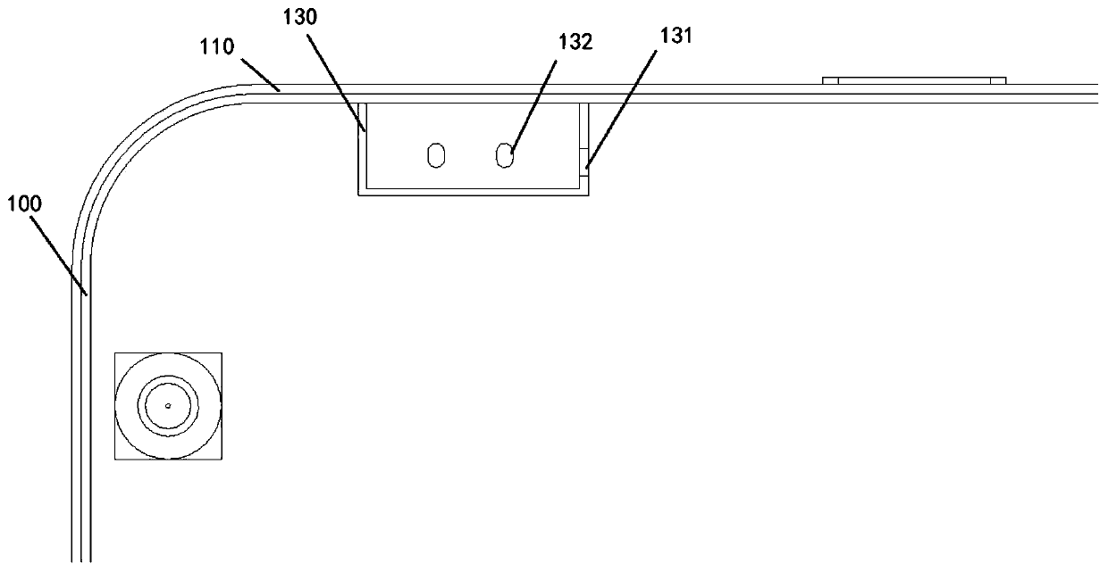
[0082] refer to Figure 6, in this embodiment, the moving direction of the driving rod 141 is the same as the moving direction of the button 121, that is, when the moving direction of the button 121 extends out of the casing 110, the moving direction of the driving rod 141 is also toward the outside of the casing 110. direction, and vice versa. In order to realize this driving mode, the driving element 140, the limiting element 130 and the key element 120 are arranged on the same side of the inner wall of the housing 110, and are attached to the same inner wall of the housing 110 to form an arrangement along the direction of the inner wall. The moving direction of the driving rod 141 is towards the inner wall of the housing 110 or facing away from the inner wall of the housing 110. Therefore, the through hole of the driving rod 141 and the guide hole 131 are strip-shaped respectively, that is, the hollow part of the through hole and the guide hole 131 is along the direction of...
Embodiment 2
[0086] In this embodiment, the difference from Embodiment 1 is that the shapes of the through hole and the guide hole 131, that is, the shape of the hollow part on the two parts are consistent with the shape of the outer contour of the driving rod 141, and the driving rod 141 follows the through hole and the The reciprocating movement of the guide hole 131 in the through direction can reduce the size requirements of the through hole and the guide hole 131 . At the same time, the driving element 140 is disposed on the side of the limiting element 130 away from the housing 110 , that is, the key element 120 , the limiting element 130 and the driving element 140 are respectively provided according to the direction of the housing 110 from outside to inside. When the driving unit 142 controls the driving rod 141 to push toward the direction of the housing 110, the driving rod 141 will also push the button element 120 toward the outside of the housing 110 until it extends out of the ...
Embodiment 3
[0089] In this embodiment, the same point as the second embodiment is that the shapes of the through hole and the guide hole 131, that is, the shape of the hollow part on the two parts is consistent with the shape of the outer contour of the driving rod 141, and the driving rod 141 is along the through hole and The penetrating direction of the guide hole 131 reciprocates. The difference between the third embodiment and the first and second embodiments is that the moving direction of the driving rod 141 in the first and second embodiments is in the same direction as the expected moving direction of the key element 120, that is, the moving direction is in the same direction, while in the first and second embodiments The movement direction of the three driving rods 141 is perpendicular to the expected movement direction of the key element 120 . In view of this, the structures of the driving rod 141 and the pallet 122 in the third embodiment are more special. Specifically, see ...
PUM
 Abstract
Description
Claims
Application Information
 - R&D
- Intellectual Property
- Life Sciences
- Materials
- Tech Scout
- Unparalleled Data Quality
- Higher Quality Content
- 60% Fewer Hallucinations
Browse by: Latest US Patents, China's latest patents, Technical Efficacy Thesaurus, Application Domain, Technology Topic, Popular Technical Reports.
© 2025 PatSnap. All rights reserved.Legal|Privacy policy|Modern Slavery Act Transparency Statement|Sitemap|About US| Contact US: help@patsnap.com


