
A swirl zone flotation machine

A flotation machine and flotation cell technology, used in flotation, solid separation and other directions, can solve the problems of affecting the flotation effect, ore particles falling off, excessive turbulence in the flow field, etc., and achieve the guarantee of flotation efficiency and flotation effect. Guaranteed effect

Active Publication Date: 2020-07-28
ANHUI UNIV OF SCI & TECH
View PDF8 Cites 0 Cited by
  • Summary
  • Abstract
  • Description
  • Claims
  • Application Information

AI Technical Summary

Problems solved by technology

At the same time, because the non-mechanical agitation flotation machine needs to ensure sufficient ore flow and suction capacity, the flow field in the flotation tank is often excessively turbulent, which will cause the mineralized ore particles to fall off during the flotation process, thereby affecting Flotation effect

Method used


Image

  • A swirl zone flotation machine
  • A swirl zone flotation machine
  • A swirl zone flotation machine

Examples


Embodiment Construction

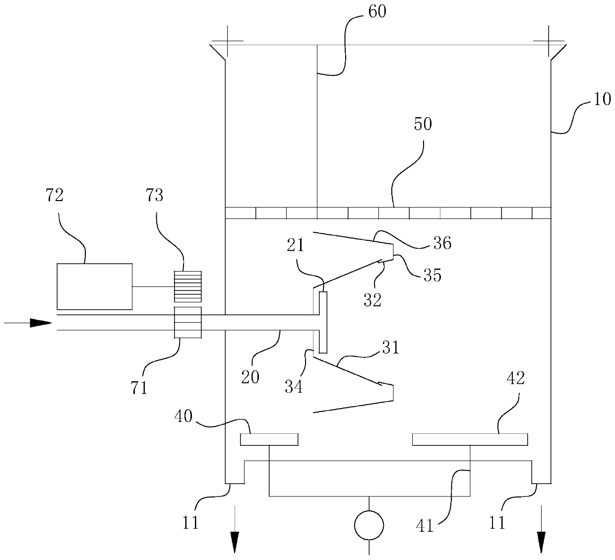
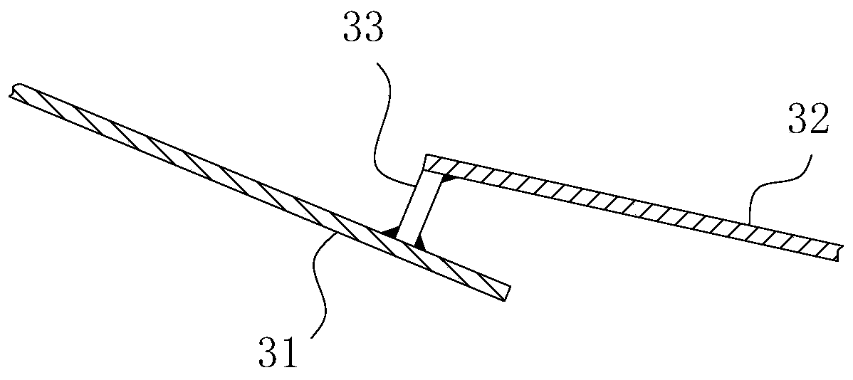
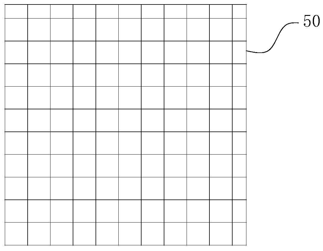
[0028] For ease of understanding, combined here Figure 1-4 , the specific embodiments of the present invention are further described as follows:

[0029] The specific components of the present invention are as follows Figure 1-4 The structure shown is an example, which is divided into several major modules, including: flotation cell 10, vertical partition 60, steady flow plate 50, rotating disk, bubble generating tube 40, rotating discharge tube 20 and driving components. in:

[0030] exist figure 1In the shown structure, the flotation cell 10 is in the shape of a square cell. In the cavity of the flotation cell 10, a vertical partition 60, a steady flow plate 50, a rotating disk and a bubble generating tube 40 are respectively arranged from top to bottom. On the left side and the right side of the bottom of the flotation tank 10, discharge pipelines 11 are respectively arranged. For the driving assembly, it includes a driving motor 72 , a driving gear 73 and a driven g...


PUM


Abstract

The invention relates to the technical field of mineral flotation, specifically to an eddy flow partition flotation machine. The flotation machine comprises a flotation cell and a rotary discharge pipe. the rotary discharge pipe can rotate around its axis; a first guiding conical surface and a second guiding conical surface are coaxially and fixedly connected at an output port of the rotary discharge pipe; the output port of the rotary discharge pipe is a radial discharge port, a discharge end of which is directed at the inner wall of the first guiding conical surface; a bonding post is arranged in the fit clearance between the first guiding conical surface and the second guiding conical surface; and a bubble generator tube is arranged at both the mineral grain blanking point of a walk-through passage and the mineral grain blanking point pointed by the large-diameter end of the second guiding conical surface. The collision efficiency between mineral grains and bubbles can be effectively improved, and finally the flotation efficiency and effect can be both greatly enhanced.

Description

technical field [0001] The invention relates to the technical field of mineral flotation, in particular to a swirling partition flotation machine. Background technique [0002] Flotation is the most important interface separation method, and it has been widely used in the fields of separation flotation of polymetallic ores, comprehensive utilization of complex ores, iron ore flotation, and non-metallic ores. The theoretical basis of various flotation processes is roughly the same, that is, due to the hydrophobic characteristics of the surface of the ore particles or the hydrophobic (air-friendly or oil) characteristics obtained after the action of the flotation agent, the ore particles will be in liquid-gas or water-oil. Agglomeration occurs at the interface. Currently the most widely used method is the froth flotation method, which includes the following processes: 1) After the ore is crushed and ground, various minerals are dissociated into individual ore particles, and t...

Claims


Application Information

Patent Timeline
Patent Type & Authority Patents(China)
IPC IPC(8): B03D1/14B03D1/24
Inventor 朱宏政黄典强位都邵善敏刘杰唐佳佳李甜王海楠
Owner ANHUI UNIV OF SCI & TECH
Learn More