Micro laser precision machining device

A precision machining and laser technology, used in laser welding equipment, metal processing equipment, manufacturing tools, etc., can solve the problems of effectively processing small processing surfaces with small thickness, inaccurate processing positioning, difficult system assembly and adjustment, etc., to achieve flatness adaptation The effect of strong performance, long processing distance and large dynamic range

Inactive Publication Date: 2019-05-21
丹阳亿仁通信设备有限公司
View PDF0 Cites 0 Cited by
  • Summary
  • Abstract
  • Description
  • Claims
  • Application Information

AI Technical Summary

Problems solved by technology

[0002] In traditional laser processing, the effective processing thickness of the workpiece is small, and the processing surface has problems such as taper and roughness. However, due to the use of the focusing lens, it is required to strictly couple the focal point of the focusing lens with the center of the microhole of the nozzle. In addition, the existing water-guided laser system There are disadvantages such as no visible light coaxial positioning indication, difficult system assembly and adjustment, imprecise processing positioning, and inability to realize random detection

Method used


Image

  • Micro laser precision machining device

Examples


Embodiment Construction

[0011] The preferred embodiments of the present invention are given below in conjunction with the accompanying drawings to describe the technical solution of the present invention in detail.

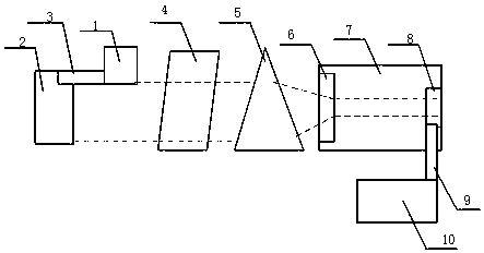
[0012] Such as figure 1 As shown, a micro-laser precision machining device includes a laser 1, a visible light source 2, a plane mirror 3, a beam expander collimator 4, an axicon prism 5, an optical window 6, a pressure fluid chamber 7 and a nozzle microhole 8, and a plane mirror 3 Located in front of the laser 1 and the visible light source 2, the laser beam emitted by the laser 1 is coupled with the beam of the visible light source 2 through the plane mirror 3, the beam expander collimator 4 is located in front of the plane mirror 3, the axicon 5 is located in front of the beam expander collimator 4, and the pressure fluid The cavity 7 is located in front of the axicon 5, the optical window 6 is located at the top of the pressure fluid cavity 7, the nozzle microhole 8 is located at the...


PUM


Abstract

The invention discloses a micro laser precision machining device. The micro laser precision machining device comprises a laser device, a visible light source, a plane mirror, a beam expanding collimator, a rotary prism, an optical window, a pressure fluid cavity and a nozzle micropore; a laser beam and a visible light beam which are coupled through the plane mirror are coaxial with the beam expanding collimator, the rotary prism, the optical window and the nozzle micropore; the laser device is a laser device of which the power range is from the watt grade to the hectowatt grade; the visible light source is a common white light source; and the beam expanding collimator is a beam expanding collimator which is of an inverted-telescope structure. According to the micro laser precision machining device, the defects that an existing water conduction laser system is high in coupling requirement for the laser focal point and the center point of a nozzle micropore, and detection is difficult are overcome, and the adaptability of the machining device to the surface flatness of a workpiece is high; and in addition, in the optical axis direction, precision focusing is not needed, parfocalization does not need to be considered, and ideal laser precision cutting, drilling and other machining can be achieved.

Description

technical field [0001] The utility model relates to a precision processing device, in particular to a micro-laser precision processing device. Background technique [0002] In traditional laser processing, the effective processing thickness of the workpiece is small, and the processing surface has problems such as taper and roughness. However, due to the use of the focusing lens, it is required to strictly couple the focal point of the focusing lens with the center of the microhole of the nozzle. In addition, the existing water-guided laser system There are disadvantages such as no visible light coaxial positioning indication, difficult system assembly and adjustment, inaccurate processing positioning, and inability to realize random detection. Contents of the invention [0003] The technical problem to be solved by the present invention is to provide a micro-laser precision machining device. [0004] The present invention solves the above-mentioned technical problems thr...

Claims


Application Information

Patent Timeline
Patent Type & Authority Applications(China)
IPC IPC(8): B23K26/064B23K26/14
Inventor 庄如苏豪
Owner 丹阳亿仁通信设备有限公司
Why Eureka
Try Eureka