
Centrifugal pump impeller manufacturing method

A centrifugal pump impeller and manufacturing method technology, which is applied in the direction of manufacturing tools, pumps, and components of pumping devices for elastic fluids, etc., can solve the problems of impeller production that is easy to be scrapped, and meet the drawing size requirements and technical requirements, operation Convenience and small size deformation effect

Inactive Publication Date: 2019-05-21
ZONGYANG COUNTY ZHONGBANG TECH INFORMATION CONSULTING CO LTD
View PDF8 Cites 1 Cited by
  • Summary
  • Abstract
  • Description
  • Claims
  • Application Information

AI Technical Summary

Problems solved by technology

[0005] The purpose of the present invention is to solve the problem that the impeller is easily scrapped in production by proposing a method for manufacturing the impeller of a centrifugal pump in view of the above-mentioned problems in the existing technology

Method used


Image

  • Centrifugal pump impeller manufacturing method
  • Centrifugal pump impeller manufacturing method
  • Centrifugal pump impeller manufacturing method

Examples


Embodiment 1

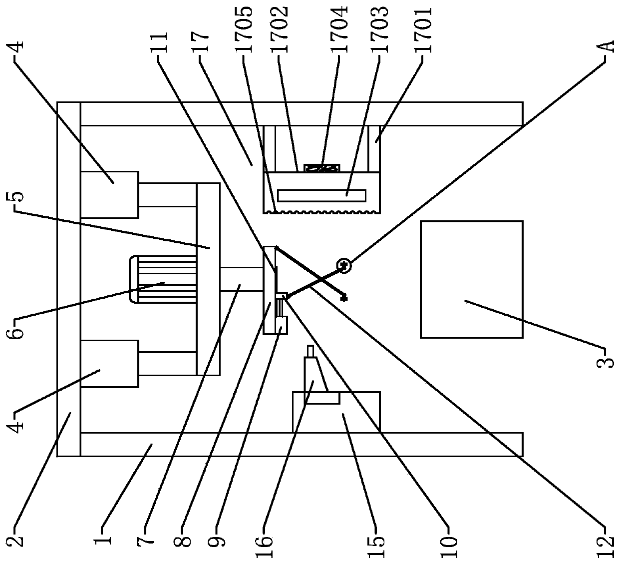
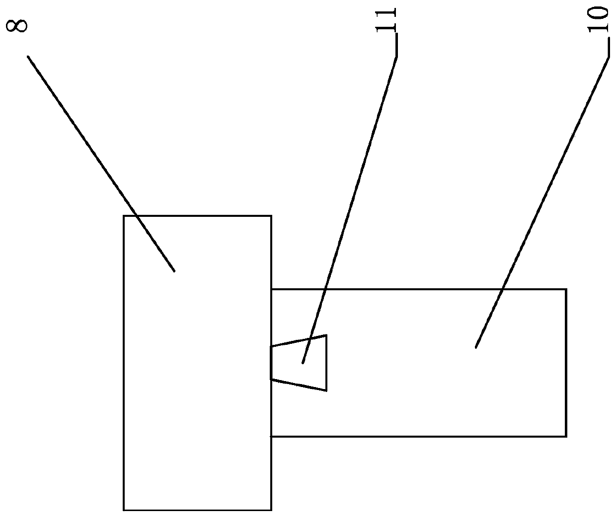
[0058] see Figure 1-6 , a spraying device, comprising a column 1, a beam 2 and a parts placement platform 3; a beam 2 is arranged above the column 1; a parts placement platform 3 is arranged between the columns 1, and a first electric telescopic device is arranged below the beam 2 Rod 4; the bottom of the first electric telescopic rod 4 is connected to the first mounting plate 5; a rotating motor 6 is installed above the center of the first mounting plate 5, and the rotating shaft 7 is connected below the rotating motor 6; below the rotating shaft 7 The second mounting plate 8 is set; the second electric telescopic rod 9 is installed at one end of the bottom surface of the second mounting plate 8, and the front end of the second electric telescopic rod 9 is provided with a slide block 10, and the slide block 10 cooperates with the slide rail 11 to slide, and the slide rail 11 is installed on the bottom surface of the second mounting plate 8; a cross bracing 12 is arranged bel...

Embodiment 2

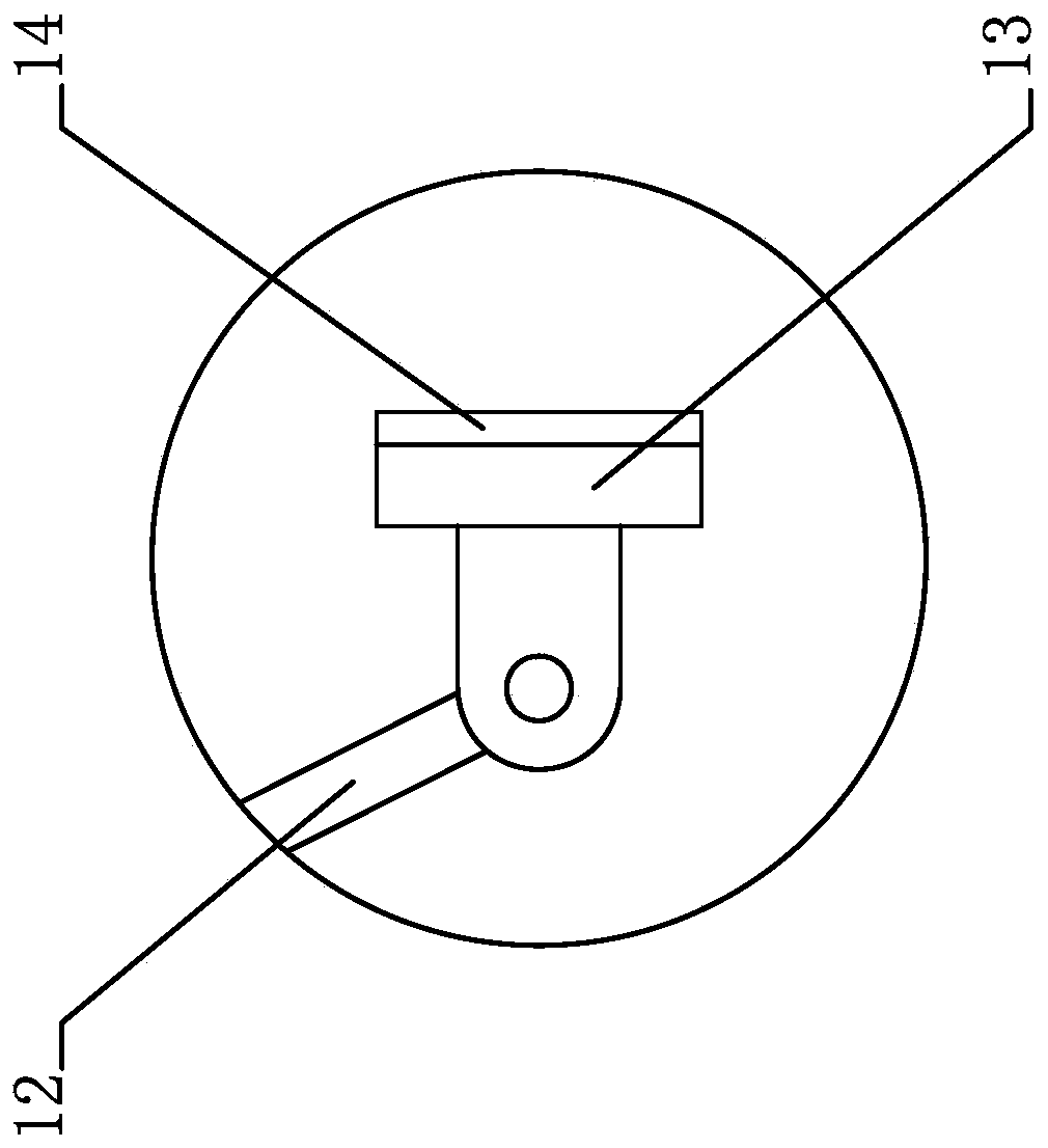
[0062] see figure 1 and Figure 7 , a spraying device, including a fixed end 1301, a movable end 1302 and a hinged ball 1303; on the basis of Embodiment 1, the support foot 13 is replaced by a fixed end 1301 fixedly connected to the cross brace 12; the fixed end 1301 is hinged The ball 1303 is connected to the movable end 1302; the outer side of the movable end 1302 is provided with an anti-skid pad 14; the supporting foot 13 with a degree of freedom of rotation makes the movable end 1302 and the fixed end 1301 rotate relatively through the hinged ball 1303, further increasing the second electric telescopic During the movement of the rod 9, the contact area between the supporting foot 13 and the inner cylinder of the part provides a more stable support.

[0063] The working principle of the present invention is: the cylindrical parts are vertically placed on the part placement table 3 directly below the cross brace 12, the second electric telescopic rod 9 is extended, and the...


PUM


Abstract

The invention provides a centrifugal pump impeller manufacturing method, and belongs to the technical field of impellers. The centrifugal pump impeller manufacturing method comprises the following steps: (S1) profiling design and manufacturing: according to a hydraulic model of a centrifugal pump, all parameters of an impeller are designed and a three-dimensional model is built; then, profiling ismanufactured by adopting a mode of combining numerical control machining with manual manufacturing; aluminum products are selected as profiling mold materials; aluminum rods with diameters below 300mm are adopted as mold materials; raw aluminum with diameters above 300 mm is adopted as mold materials; molten aluminum is prepared according to the standard; and workpieces are cast; (S2) inspectionof initial products: the workpieces obtained by casting or numerical control cutting are inspected by adopting eyes and a metal defect detector; and (S3) deformation protection before heat treatment:the workpieces obtained by casting or numerical control cutting are put on a flat support; and when the workpieces enter or exit from a furnace, the flat support is lifted to prevent thermal deformation of the workpieces during lifting. The method has the advantage of difficult waste in impeller production.

Description

technical field [0001] The invention belongs to the technical field of impellers, in particular to a method for manufacturing impellers of centrifugal pumps. Background technique [0002] Centrifugal pumps work by rotating the impeller to cause the water to move centrifugally. Before starting the pump, the pump casing and the suction pipe must be filled with water, and then the motor is started to drive the impeller and the water to rotate at a high speed. The water undergoes centrifugal motion and is thrown to the outer edge of the impeller, and flows through the volute pump casing. The pressure water pipeline flowing into the water pump. [0003] The impeller is the core part of the centrifugal pump. Its rotating speed is higher than that of the centrifugal pump, and the force is greater. The blades on the impeller play a major role. The impeller must pass the static balance test before assembly. The inner and outer surfaces of the impeller are required to be smooth to r...

Claims


Application Information

Patent Timeline
IPC IPC(8): B23P15/00B22C9/22C21D9/00B05D7/14F04D29/24
CPCY02P10/20
Inventor 汪慧敏
Owner ZONGYANG COUNTY ZHONGBANG TECH INFORMATION CONSULTING CO LTD
Features
  • Generate Ideas
  • Intellectual Property
  • Life Sciences
  • Materials
  • Tech Scout
  • Unparalleled Data Quality
  • Higher Quality Content
  • 60% Fewer Hallucinations
Learn More